Fisher and Paykel RDV3-304-N Data Sheet Dual Fuel Range
Fisher and Paykel RDV3-304-N Manual
 |
View all Fisher and Paykel RDV3-304-N manuals
Add to My Manuals
Save this manual to your list of manuals |
Fisher and Paykel RDV3-304-N manual content summary:
- Fisher and Paykel RDV3-304-N | Data Sheet Dual Fuel Range - Page 1
to cabinetry face - flush f Height from countertop to top of pan supports g Height of rear trim H Depth of rear trim i Height from guide, dimensions may vary by ±2mm (1/16''). Please read the installation manual for detailed information on installing the product. For full installation instructions - Fisher and Paykel RDV3-304-N | Data Sheet Dual Fuel Range - Page 2
CLEARANCES INDICATES PRODUCT DATUM DATE: 14.07.2020 IMPORTANT NOTE: Throughout this guide, dimensions may vary by ±2mm (1/16''). Please read the installation manual for detailed information on installing the product. For full installation instructions & specifications visit fisherpaykel.com - Fisher and Paykel RDV3-304-N | Data Sheet Dual Fuel Range - Page 3
4 cu.ft Electrical Supply Service Max Current Draw Receptacle 120/ manual. 2" DATE: 14.07.2020 IMPORTANT NOTE: Throughout this guide, dimensions may vary by ±2mm (1/16''). Please read the installation manual for detailed information on installing the product. For full installation instructions - Fisher and Paykel RDV3-304-N | Data Sheet Dual Fuel Range - Page 4
to cabinetry face - flush f Height from countertop to top of pan supports g Height of rear trim H Depth of rear trim i Height from guide, dimensions may vary by ±2mm (1/16''). Please read the installation manual for detailed information on installing the product. For full installation instructions - Fisher and Paykel RDV3-304-N | Data Sheet Dual Fuel Range - Page 5
CLEARANCES INDICATES PRODUCT DATUM DATE: 14.07.2020 IMPORTANT NOTE: Throughout this guide, dimensions may vary by ±2mm (1/16''). Please read the installation manual for detailed information on installing the product. For full installation instructions & specifications visit fisherpaykel.com - Fisher and Paykel RDV3-304-N | Data Sheet Dual Fuel Range - Page 6
Capacity 113L Electrical Supply Service Max Current Draw Receptacle manual. DATE: 14.07.2020 IMPORTANT NOTE: Throughout this guide, dimensions may vary by ±2mm (1/16''). Please read the installation manual for detailed information on installing the product. For full installation instructions
-
 1
1 -
 2
2 -
 3
3 -
 4
4 -
 5
5 -
 6
6
 |
 |
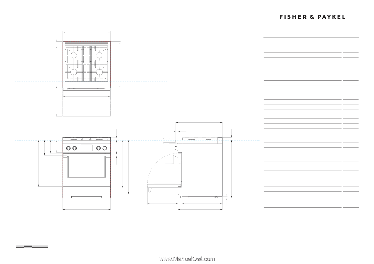
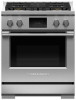
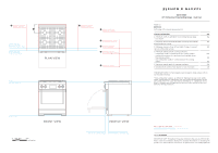
DATA SHEET
30" Professional Freestanding Range - Dual Fuel
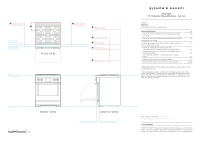
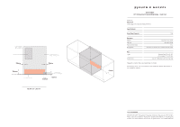
INDICATES CAVITY CLEARANCES
---------------
INDICATES PRODUCT DATUM
--------------------
DATE:
14.07.2020
IMPORTANT NOTE: Throughout this guide, dimensions may vary by
±
2mm (1/16'').
Please read the installation manual for detailed information on installing the
product. For full installation instructions & specifications visit fisherpaykel.com
29 7/8"
B
29 1/8"
g
35 3/4" -
36 3/4"
p
n
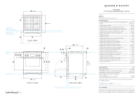
FRONT VIEW
PLAN VIEW
PROFILE VIEW
L
c
o
J
u
a
f
I
K
q
D
e
r
m
Model no:
RDV±-±04
(refer page 4 for metric measurements)
Product Dimensions
in
a
Height of range (from floor to cooktop, excluding grates and
rear trim)
min 35 3/4"
max 36 3/4"
B
Overall width of range
29 7/8"
c
Overall depth of range (excluding handle and dials)
29 1/8"
d
Depth from rear of chassis to cabinetry face - projecting
25 3/8"
e
Depth from rear of chassis to cabinetry face - flush
27 11/16"
f
Height from countertop to top of pan supports
1 9/16"
g
Height of rear trim
1 3/4"
H
Depth of rear trim
2 7/8"
i
Height from countertop to bottom of control panel
7 3/4"
j
Height from countertop to top of door
8 1/8"
k
Height from countertop to centre of handle
9 7/16"
l
Height from countertop to bottom of door
29"
m
Height from countertop to top of lower panel
29 15/16"
n
Height from countertop to bottom of lower panel
33 5/8"
o
Thickness of handle (not including standoffs)
1 1/4"
p
Width of handle (including standoffs)
29 1/8"
q
Depth of handle (measured from front of door)
2 7/8"
r
Depth of front of cooktop to control panel
1 7/16"
s
Height of cooktop front face
1 3/8"
t
Height from top of cooktop to control panel
2"
u
Depth of open door to cabinetry face - flush
19 1/8"
v
Adjustable feet height
min 1/2"
max 1 1/2"
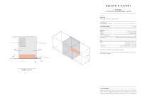
Cavity Dimensions
mm
Overall width of cavity
min 30"
Overall depth of cavity for projecting control panel
max 25 3/8"
Overall depth of cavity for flush control panel
max 27 11/16"
Maximum height of from floor to countertop:
- for level counter
- with range levelling legs fully extended
35 3/4"
36 3/4"
IMPORTANT NOTE: For full installation and clearance details please refer to
our installation manual.
T
H
S
u
DATUM : FLOOR
DATUM :
TOP OF
COUNTERTOP
CABINET FACE FOR INSTALLATION
WITH PROJECTING CONTROL PANEL
CABINET FACE FOR INSTALLATION
WITH FLUSH CONTROL PANEL
CABINET FACE FOR
INSTALLATION WITH
PROJECTING CONTROL PANEL
CABINET FACE FOR
INSTALLATION WITH
FLUSH CONTROL PANEL
29 1/8"
c
29 7/8"
B
V
0
5
10
20
inches