Fender Princeton 112 Plus Owners Manual - Page 3
Princeton 112 Plus Front Panel Functions - footswitch
 |
View all Fender Princeton 112 Plus manuals
Add to My Manuals
Save this manual to your list of manuals |
Page 3 highlights
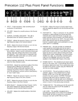
Princeton 112 Plus Front Panel Functions A. INPUT - A high impedance, high sensitivity plug-in connection for instruments. B. VOLUME - Adjusts the overall loudness of the Normal Channel. C. NORMAL CHANNEL INDICATOR - This LED is illuminated when the Normal Channel is active. D. TREBLE - Adjusts the amount of boost or cut in the high frequency range of the Normal Channel. E. BASS - Adjusts the amount of boost or cut in the low frequency range of the Normal Channel. F. GAIN - Adjusts the amount of preamp amplification in the Drive Channel. Cleaner sound is achieved at lower gain settings; high gain settings will produce more sustain and distortion. This control works in conjunction with the DRIVE VOLUME control (item L) to set the overall loudness of the Drive Channel. G. DRIVE CHANNEL INDICATOR -This LED is illuminated when the Drive Channel is active. H. CONTOUR - Adjusts the overall tone quality of the Drive Channel without affecting the signal level. Low CONTOUR settings will provide emphasis in the midrange frequencies whereas a higher setting will notch the midrange to produce sounds characteristics of most "metal" music. I. TREBLE - Adjusts the amount of boost or cut in the high frequency range of the Drive Channel. J. BASS - Adjusts the amount of boost or cut in the low frequency range of the Drive Channel. K. DRIVE SELECT - Activates the Drive Channel. NOTE: This switch disables the optional Channel Select Footswitch and the Normal Channel controls. L. VOLUME - Adjusts the overall loudness of the Drive Channel. M. REVERB - Adjusts the amount of reverb signal mixed with the original dry signal for both the Normal and Drive Channels. N. FOOTSWITCH - Plug in connection for the optional footswitch to select between the Normal and Drive Channels and to switch the Reverb on and off. For proper operation of the footswitch, the DRIVE SELECT switch (item K) should be out. NOTE: Any good quality patch cable will work with the remote footswitch, however, a speaker grade cord is preferable to a coax guitar cable if it is availability. O. PREAMP OUT - This jack provides an unbalanced output signal from the preamp and can be used in conjunction with the POWER AMP IN jack (item P) as a patch point for effects units (i.e. as an effects loop). This signal can also be used to feed recording and sound reinforcement mixers. Additionally it can drive another amplifier as a slave by connecting a standard guitar cable from the PREAMP OUT jack of the master amplifier to the POWER AMP IN jack of the slave. P. POWER AMP IN - This unbalanced jack inputs signal directly to the power amp. It automatically disconnects the preamp signal when used. This is useful when using the effects loop option or when using the PRINCETON 112 Plus as a slave amplifier. Q. HEADPHONES - This jack provides an output to standard stereo or mono headphones for private listening. NOTE: Use of this jack automatically disables the main speaker. CAUTION: Prolonged listening at high levels may be hazardous to your hearing! This jack can also be used as an unbalanced line output, which is post effects loop, by using either a stereo or mono 1/4 inch phone plug connection. R. POWER SWITCH - This switch turns the AC power ON and OFF. When the switch is OFF the amplifier is completely shut down. LINE CORD - This amplifier is equipped with a grounding type supply cord to reduce the possibility of shock hazard. Be sure to connect it to a grounded receptacle. DO NOT ALTER THE AC PLUG.
-
 1
1 -
 2
2 -
 3
3 -
 4
4
 |
 |
