Epson TM-T20II UB-E04 Users Manual - Page 6
Caution
 |
View all Epson TM-T20II manuals
Add to My Manuals
Save this manual to your list of manuals |
Page 6 highlights
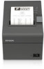
Part Names LED (green) Ethernet LED (yellow) USB Type-A Push button interface connector connector Note: Do not connect any equipment other than the Wireless LAN unit to the USB Type-A connector. Printer settings If the TM printer has a memory switch or a dip switch for "#25 pin reset signal" or "#31 pin reset signal" setting, do not change the setting from Enable. Changing the setting may result in the printer to stop operating. Switch and function names may vary depending on the printer. For details, see the Technical Reference Guide of the printer. CAUTION: Do not remove the interface board from or install the interface board into TM printer. Doing so may cause malfunction of the printer or the interface board. Connecting the Cables 1. Make sure both the printer and the host computer are turned off. 2. Plug the Ethernet cable securely into the UB-E04's Ethernet connector until you feel it click. CAUTION: Do not connect a telephone line, a display module cable, or a drawer kick cable to the Ethernet connector. Note: When the UB-E04 is installed, a customer display connector on the TM printer cannot be used. 3. Connect the power supply cable to the printer. 2
-
 1
1 -
 2
2 -
 3
3 -
 4
4 -
 5
5 -
 6
6 -
 7
7 -
 8
8
 |
 |
