Epson Powerspan Desktop Product Information Guide - Page 4
Jumper Settings, Simm Installation, Epson Powerspan Dt - 4
 |
View all Epson Powerspan Desktop manuals
Add to My Manuals
Save this manual to your list of manuals |
Page 4 highlights
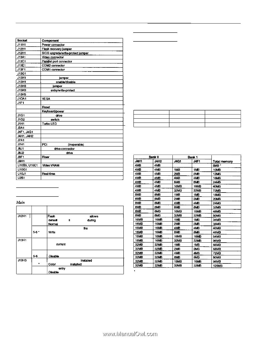
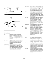
EPSON PowerSpan DT System board components and connectors Jl3Gl Jl3Hl 1 J13Hl Jl3H3 Jl3H3 J13H5 JIDAI JIFI JlF2 JlF3 JIG1 JIG2 JlHl J3Al J4F1, J4Gl J4H1, J4H2 J7Al J7Hl J6Jl J6J2 J9Fl Jgfil UiOB5, UIOCI UloGl UlaJl U2Bl j Mouse connector I CMOS clear jurrper j Password enable/disabfe jumper Monitor jumper Setup entry/write-protect jumper Keyboard connector VESA feature connector Speaker Reset Ke-erLED Hard disk drive LED 1 Turbo swftch I hb0LED Auxiliary Ian SIMM bank 1 SIMM bank 0 CPU clock speed jumper (DO NOT CHANGE SETTING) FCI IDE connector (inoperabfe) Diskette drive connecfor AT IDE hard disk drive connector Fflser card connector Power connector video VHAM upgrade sockets BIOS I FleaI-time clock Processor SIMM lnstallation Your computer comes with 8MB of memory on two 4MB SIMMs. You can increase the memory up to 128MB using 1MB, 2MB, 4MB, 8MB, 16MB, and 32MB SIMMs (when readily available). The SIMM sockets are organized in two banks (Bank 0 and Bank 1) consisting of two sockets each. You must install the same type of SIMM in a bank. The SIMMs you install must be 32-bit or 36-bit, 72-pin, 70ns, tin-plated, fast-page mode, parity/no parity DRAM. The table below lists the 16MB and 32MB SIMMs that are approved for use in your system. You can install these SIMMs or their equivalents. Manufacturer Samsung Samsung Hitachi Description 16MB; with parity 16MB; no parity 32MB; with parity Part number KM41 COOBJ-7 KMM5324000BG-7 HM5117400J7 The table below lists possible combinations of SIMMs you can install; do not use any configuration other than one of those listed in the table. SIMM configurations Jumper Settings Main system board jumper settings Jumper I I I number Settings Function Jl2Hl 1 l-2 1 Flaeh memory recovery mode; atfows recovery of the defauit BIOS if it is corrupted dutlng an upgrade 2-3 l Normal flash memory operation 4-5 Enable BIOS upgrades to tfte flash memory 5-6' Write protect the flash memory to prevent BIOS Jl3Hl l-2 l 2-3 Jl3H3 4-5 l 15-6 1 l-2 2-3 * 4-5 l 5-6 Upgrades Normal CMOS operation Clear current CMOS settings to reset to the factory default settings Enable the current password 1 Disable the cum&password 1 Monochrome monitor Is installed Color monitor Is instafled Enable entry Into the Setup program Disable entry into the Setup program l Factory setting * Factory configuration EPSON PowerSpan DT - 4 3/94
-
 1
1 -
 2
2 -
 3
3 -
 4
4 -
 5
5 -
 6
6 -
 7
7 -
 8
8 -
 9
9 -
 10
10 -
11
 |
 |