Electrolux ECCG3672AS Installation Instructions English - Page 4
Product Dimensions, Cabinet clearances
 |
View all Electrolux ECCG3672AS manuals
Add to My Manuals
Save this manual to your list of manuals |
Page 4 highlights
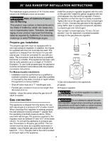
36" GAS RANGETOP INSTALLATION INSTRUCTIONS Product Dimensions Cabinet clearances A 912.4 mm B1 max: 688 mm min: 681.5 mm C 190.5 mm D 46.5 mm E 604 mm F 241 mm 35 15/16" max: 27 1/8" min: 26 13/16" 7 1/2" 1 13/16" 23 12/16" 9 1/2" 1. Dimension B and clearance G (next table) varies according to the presence of the rear spacers and its screws: the maximum is obtained with the rear spacer and the minimum without it. The rear spacer can be removed in case of island installation or if the back wall is non-combustible. NOTE: Clearances from non-combustible materials are not part of the ANSI Z21.1 scope and are not certified by CSA. If removing the rear spacers remove its screws as well. The total thickness of the spacers and the screw heads is 0.256" (6.5 mm). F 914 mm 36" G1 max: 619 mm min: 612.5 mm H min. 508 mm max: 24 3/8" min: 24 1/8" min. 20" I min. 457 mm min. 18" J see notes below K max. 330 mm max. 13" L max. 330 mm max. 13" M min. 914 mm min. 36" N 190.5 mm 7 1/2" Clearance J can have the following values: • J = 36" / 914 mm minimum clearance between the top of the cooking surface and the bottom of an unprotected wood or metal cabinet. • J = 30" / 762 mm minimum when the bottom of wood or metal cabinet is protected by not less than 1/4-inch-thick flame-retardant millboard covered with not less than No. 28 MSG sheet steel, 0.015-inch-thick stainless steel, 0.024-inch-thick aluminum, or 0.020-inch-thick copper. Clearances from non-combustible materials are not part of the ANSI Z21.1 scope and are not certified by CSA. Clearances of less than 30'' should be approved by the local codes and/or by the local authority having jurisdiction. 4
-
 1
1 -
 2
2 -
 3
3 -
 4
4 -
 5
5 -
 6
6 -
 7
7 -
 8
8 -
 9
9 -
 10
10 -
11
-
12
-
13
-
14
-
15
-
16
-
17
-
18
-
19
-
20
-
21
-
22
-
23
-
24
-
25
-
26
-
27
-
28
-
29
-
30
-
31
-
32
-
33
-
34
-
35
-
36
-
37
-
38
-
39
-
40
-
41
-
42
-
43
-
44
 |
 |
