Dell P780 Service Manual - Page 10
Disassembly, A And D, Board Removal, Cabinet Removal, Service Position
 |
View all Dell P780 manuals
Add to My Manuals
Save this manual to your list of manuals |
Page 10 highlights
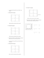
P780 SECTION 2 DISASSEMBLY 2-1. CABINET REMOVAL Two claws Cabinet PUSH PUSH 2-2. SERVICE POSITION A board D board Two screws (BVTP 4 x 16) 2-3. A and D BOARD REMOVAL A board D board Chassis base Five screws (BVTP 3 x 12) One screw (BVTT 4 x 8) Cable stopper 1 When the D-board is placed in service position, the Safety Earth Wire (green and yellow wire) is disconnected. 2 After service is completed and the D-board reinstalled, the Safety Earth Wire must be reattached to the chassis with the proper screw. This must be confirmed before any subsequent procedures are attempted. Four screws (BVTP) 3 x 8) EMI Shield Three screws (BVTP) 3 x 8) - 10 - Holder
-
 1
1 -
2
-
3
-
4
-
 5
5 -
 6
6 -
 7
7 -
 8
8 -
 9
9 -
 10
10 -
 11
11 -
 12
12 -
 13
13 -
 14
14 -
 15
15 -
16
-
17
-
18
-
19
-
20
-
21
-
22
-
23
-
24
-
25
-
26
-
27
-
28
-
29
-
30
-
31
-
32
-
33
-
34
-
35
-
36
-
37
-
38
-
39
-
40
-
41
-
42
-
43
-
44
-
45
-
46
-
47
-
48
-
49
-
50
-
51
-
52
-
53
-
54
-
55
-
56
-
57
-
58
-
59
-
60
-
61
 |
 |

— 10 —
P780
2-3.
A and D
BOARD REMOVAL
2-1.
CABINET REMOVAL
2-2.
SERVICE POSITION
SECTION
2
DISASSEMBLY
1
When the D-board is
placed in service
position, the Safety Earth
Wire (green and yellow
wire) is disconnected.
2
After service is
completed and the
D-board reinstalled, the
Safety Earth Wire must
be reattached to the
chassis with the proper
screw.
This must be
confirmed before any
subsequent procedures
are attempted.
A board
D board
Cabinet
Two screws
(BVTP 4 x 16)
Two claws
PUSH
PUSH
EMI Shield
Four screws
(BVTP) 3 x 8)
Three screws
(BVTP) 3 x 8)
Cable stopper
Five screws
(BVTP 3 x 12)
D board
One screw
(BVTT 4 x 8)
Holder
A board
Chassis base