Dell OptiPlex 7080 Tower Service Manual - Page 18
Disassembly and reassembly, Side cover, Removing the side cover
 |
View all Dell OptiPlex 7080 manuals
Add to My Manuals
Save this manual to your list of manuals |
Page 18 highlights
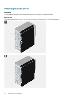
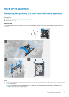
4 Disassembly and reassembly Topics: • Side cover • Front bezel • Hard-drive assembly • 3.5 in. hard-drive assembly • Solid-state drive • Memory modules • SD card reader (optional) • Processor fan and heat-sink assembly • Processor • Graphics card • Graphical processing unit • Coin-cell battery • WLAN card • Slim optical-drive • Slim optical-drive bracket • Chassis fan • VR heat sink • Speaker • Power button • Power-supply unit • Intrusion switch • Optional I/O modules (Type C/ HDMI/VGA/DP/Serial) • System board Side cover Removing the side cover Prerequisites 1. Follow the procedure in before working inside your computer. NOTE: Ensure that you remove the security cable from the security-cable slot (if applicable). About this task The following images indicate the location of the side cover and provide a visual representation of the removal procedure. 18 Disassembly and reassembly
-
 1
1 -
2
-
3
-
4
-
5
-
6
-
7
-
8
-
9
-
10
-
11
-
12
-
 13
13 -
 14
14 -
 15
15 -
 16
16 -
 17
17 -
 18
18 -
 19
19 -
 20
20 -
 21
21 -
 22
22 -
 23
23 -
24
-
25
-
26
-
27
-
28
-
29
-
30
-
31
-
32
-
33
-
34
-
35
-
36
-
37
-
38
-
39
-
40
-
41
-
42
-
43
-
44
-
45
-
46
-
47
-
48
-
49
-
50
-
51
-
52
-
53
-
54
-
55
-
56
-
57
-
58
-
59
-
60
-
61
-
62
-
63
-
64
-
65
-
66
-
67
-
68
-
69
-
70
-
71
-
72
-
73
-
74
-
75
-
76
-
77
-
78
-
79
-
80
-
81
-
82
-
83
-
84
-
85
-
86
-
87
-
88
-
89
-
90
-
91
-
92
-
93
-
94
-
95
-
96
-
97
-
98
-
99
-
100
 |
 |
