Dell OptiPlex 5090 Tower Setup and Specifications - Page 11
System board Layout
 |
View all Dell OptiPlex 5090 manuals
Add to My Manuals
Save this manual to your list of manuals |
Page 11 highlights
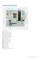
System board Layout 1. Intrusion switch connector 2. Video connector 3. ATX CPU power connector 4. Memory module connector 5. Memory module connector 6. Power button connector 7. SD card reader connector 8. ATX system power connector 9. M.2 PCIe SSD connector 10. Coin-cell battery 11. SATA3 connector (white) 12. SATA0 connector (blue) 13. M.2 WLAN connector 14. M.2 PCIe SSD connector 15. PCIe x4 (Slot4) 16. PCIe x16 (Slot3) 17. PCIe x1 (Slot2) 18. PCIe x1 (Slot1) 19. Type-C connector 20. Processor socket 21. Keyboard and Mouse serial connector Views of OptiPlex 5090 Tower 11
-
 1
1 -
2
-
3
-
4
-
5
-
 6
6 -
 7
7 -
 8
8 -
 9
9 -
 10
10 -
 11
11 -
 12
12 -
 13
13 -
 14
14 -
 15
15 -
 16
16 -
17
-
18
-
19
-
20
-
21
-
22
-
23
-
24
 |
 |
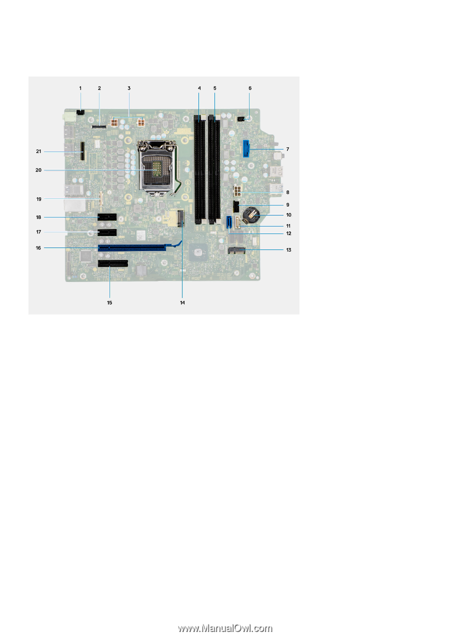
System board Layout
1.
Intrusion switch connector
2.
Video connector
3.
ATX CPU power connector
4.
Memory module connector
5.
Memory module connector
6.
Power button connector
7.
SD card reader connector
8.
ATX system power connector
9.
M.2 PCIe SSD connector
10.
Coin-cell battery
11.
SATA3 connector (white)
12.
SATA0 connector (blue)
13.
M.2 WLAN connector
14.
M.2 PCIe SSD connector
15.
PCIe x4 (Slot4)
16.
PCIe x16 (Slot3)
17.
PCIe x1 (Slot2)
18.
PCIe x1 (Slot1)
19.
Type-C connector
20.
Processor socket
21.
Keyboard and Mouse serial connector
Views of OptiPlex 5090 Tower
11