Dell OptiPlex 5090 Small Form Factor Service Manual - Page 56
Removing the system board, PCIe x16 Slot2 and PCIe x4 Slot1
 |
View all Dell OptiPlex 5090 manuals
Add to My Manuals
Save this manual to your list of manuals |
Page 56 highlights
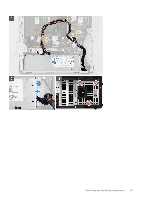
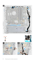
10. SATA 0 connector 11. SATA 1 connector 12. ATX system power connector 13. SATA 3 connector 14. Internal speaker cable connector 15. Coin-cell battery 16. PCIe x16 (Slot2) and PCIe x4 (Slot1) 17. PS/2 KB/Mouse Connector 18. Processor socket Removing the system board Prerequisites 1. Follow the procedure in before working inside your computer. 2. Remove the side cover. 3. Remove the front bezel. 4. Remove the 2.5/3.5-inch hard-drive caddy. 5. Remove the graphics card. 6. Remove the solid-state drive. 7. Remove the WLAN card. 8. Remove the fan assembly. 9. Remove the memory modules. 10. Remove the processor. About this task The following images indicate the location of the system board and provide a visual representation of the removal procedure. 56 Removing and installing components
-
 1
1 -
2
-
3
-
4
-
5
-
6
-
7
-
8
-
9
-
10
-
11
-
12
-
13
-
14
-
15
-
16
-
17
-
18
-
19
-
20
-
21
-
22
-
23
-
24
-
25
-
26
-
27
-
28
-
29
-
30
-
31
-
32
-
33
-
34
-
35
-
36
-
37
-
38
-
39
-
40
-
41
-
42
-
43
-
44
-
45
-
46
-
47
-
48
-
49
-
50
-
 51
51 -
 52
52 -
 53
53 -
 54
54 -
 55
55 -
 56
56 -
 57
57 -
 58
58 -
 59
59 -
 60
60 -
 61
61 -
62
-
63
-
64
-
65
-
66
-
67
-
68
-
69
-
70
-
71
-
72
-
73
-
74
-
75
-
76
-
77
-
78
-
79
-
80
-
81
-
82
-
83
-
84
-
85
-
86
-
87
-
88
-
89
-
90
-
91
 |
 |
