Dell Latitude 7400 2-in-1 Service Manual
Dell Latitude 7400 2-in-1 Manual
 |
View all Dell Latitude 7400 2-in-1 manuals
Add to My Manuals
Save this manual to your list of manuals |
Dell Latitude 7400 2-in-1 manual content summary:
- Dell Latitude 7400 2-in-1 | Service Manual - Page 1
Dell Latitude 7400 2-in-1 Service Manual Regulatory Model: P110G Regulatory Type: P110G001 August 2020 Rev. A02 - Dell Latitude 7400 2-in-1 | Service Manual - Page 2
data and tells you how to avoid the problem. WARNING: A WARNING indicates a potential for property damage, personal injury, or death. © 2019 2020 Dell Inc. or its subsidiaries. All rights reserved. Dell, EMC, and other trademarks are trademarks of Dell Inc. or its subsidiaries. Other trademarks may - Dell Latitude 7400 2-in-1 | Service Manual - Page 3
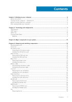
on your computer 5 Safety instructions...5 Turning off your computer - Windows 10...5 Before working inside your computer...6 After working inside your computer...6 Chapter 2: Technology and components 7 USB features...7 USB Type-C...9 HDMI 1.4a...10 Corning Gorilla Glass...11 Benefits...11 - Dell Latitude 7400 2-in-1 | Service Manual - Page 4
keyboard...82 Installing the keyboard...87 Palmrest assembly...91 Chapter 5: Troubleshooting...94 Enhanced Pre-Boot System Assessment (ePSA) diagnostics 94 media and recovery options...96 WiFi power cycle...96 Flea power release...97 Chapter 6: Getting help...98 Contacting Dell...98 4 Contents - Dell Latitude 7400 2-in-1 | Service Manual - Page 5
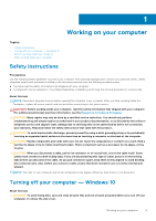
working inside the troubleshooting and simple repairs as authorized in your product documentation, or as directed by the online or telephone service and support team. Damage due to servicing that is not authorized by Dell is not covered by your warranty. Read and follow the safety instructions - Dell Latitude 7400 2-in-1 | Service Manual - Page 6
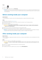
About this task To avoid damaging your computer, perform the following steps before you begin working inside the computer. Steps 1. Ensure that you follow the Safety Instruction. 2. Ensure that your work surface is flat and clean to prevent the computer cover from being scratched. 3. Turn off - Dell Latitude 7400 2-in-1 | Service Manual - Page 7
between host computers and peripheral devices like mice, keyboards, external drivers, and printers. Table 1. USB evolution Type Data Transfer devices ● New power management features ● Full-duplex data transfers and support for new transfer types ● Backward USB 2.0 compatibility ● New connectors - Dell Latitude 7400 2-in-1 | Service Manual - Page 8
5-10 times the bandwidth available, USB video solutions should work that much better. Single-link DVI requires almost 2Gbps throughput ● Portable USB 3.0/USB 3.1 Gen 1 Hard Drives ● USB 3.0/USB 3.1 Gen 1 Drive Docks & Adapters ● USB 3.0/USB 3.1 Gen 1 Flash Drives & Readers ● USB 3.0/USB 3.1 Gen 1 - Dell Latitude 7400 2-in-1 | Service Manual - Page 9
. USB Type-C ports can support a variety of different protocols using "alternate modes," which allows you to have adapters that can output HDMI, VGA of power - that'll charge your phone, but that's about it. A laptop might require up to 60 watts, for example. The USB Power Delivery specification ups - Dell Latitude 7400 2-in-1 | Service Manual - Page 10
any dock, display or data device like an external hard drive. Thunderbolt 3 uses a USB Type-C connector/port to connect to supported peripherals. users to take full advantage of their IPenabled devices without a separate Ethernet cable. ● Audio Return Channel - Allows an HDMI-connected TV with - Dell Latitude 7400 2-in-1 | Service Manual - Page 11
, and confusion of multiple cables currently used in A/V systems. ● HDMI supports communication between the video source (such as a DVD player) and the ● Ideal protective cover for electronic displays in: ○ Smartphones ○ Laptop and tablet computer screens ○ Wearable devices ● Touchscreen devices ● - Dell Latitude 7400 2-in-1 | Service Manual - Page 12
** Core index is used for FSM-based measurements since it is unaffected by ion-exchange conditions. Chemical Durability Durability is measured via weight loss per surface area after immersion in the solvents shown below. Values are highly dependent upon actual testing conditions. Data reported is - Dell Latitude 7400 2-in-1 | Service Manual - Page 13
Electrical Table 6. Electrical Frequency (MHz) 54 163 272 272 490 599 912 1499 1977 2466 2986 Dielectric Constant 7.08 7.01 7.01 7.00 7.99 7.97 7.01 6.99 6.97 6.96 6.96 Loss Tangent 0.009 0.010 0.011 0.010 0.010 0.011 0.012 0.012 0.014 0.014 0.014 Terminated coaxial line similar to that outlined - Dell Latitude 7400 2-in-1 | Service Manual - Page 14
3 Major components of your system 1. Base cover 2. Heatsink shield 14 Major components of your system - Dell Latitude 7400 2-in-1 | Service Manual - Page 15
9. Palmrest assembly 10. Coin cell 11. WLAN card 12. WWAN card 13. WWAN shield 14. Solid state drive 15. SSD shield NOTE: Dell provides a list of components and their part numbers for the original system configuration purchased. These parts are available according to warranty coverages purchased by - Dell Latitude 7400 2-in-1 | Service Manual - Page 16
screwdriver ● Plastic scribe ● T-30 torx screwdriver NOTE: The #0 screw driver is for screws 0-1 and the #1 screw driver is for screws 2-4. Screw List The following table shows the screw list and the images for Dell Latitude 7400 2-in-1, for different components and locations. Table 7. Screw Size - Dell Latitude 7400 2-in-1 | Service Manual - Page 17
Table 7. Screw Size List (continued) Component Screw type WWAN card M2x2 Fan M2x2 Speakers Heatsink Display assembly M1.6x1.4 M1.6x2.5 M2.5x3.5 Battery ● M1.6x4.5 ● M2x3 System board ● M2x2 ● M2x4 ● M2x3 Quantity 1 1 3 4 6 ●1 ●4 ●2 ●2 ●5 Keyboard M1.6x1.5 ●1 ●2 ● 40 SD memory card - Dell Latitude 7400 2-in-1 | Service Manual - Page 18
Installing the SD memory card Steps Insert the SD memory card into its slot [1] until it clicks into place [2]. 18 Removing and installing components - Dell Latitude 7400 2-in-1 | Service Manual - Page 19
SIM card tray Removing the SIM card tray NOTE: This procedure applies for models that are shipped with WWAN card only. Steps 1. Insert a paperclip or a SIM card removal tool into the pinhole on the SIM card tray [1]. 2. Push the pin to disengage the lock and eject the SIM card tray [2]. 3. Pull the - Dell Latitude 7400 2-in-1 | Service Manual - Page 20
Installing the SIM card tray Steps Install the SIM card tray into its slot on the computer [1] and push to lock it in place [2]. 20 Removing and installing components - Dell Latitude 7400 2-in-1 | Service Manual - Page 21
Base cover Removing the base cover Prerequisites 1. Follow the procedure in before working inside your computer. 2. Remove the SD memory card. Steps 1. Loosen the 10 captive screws that secure the base cover to the computer. Removing and installing components 21 - Dell Latitude 7400 2-in-1 | Service Manual - Page 22
2. Use a plastic scribe [1] to pry the base cover along the recess points located in the hinge indents as shown in the image. 3. Pry the base cover along the edges from the top side [2] to separate the base cover from the computer [2]. CAUTION: Do not pull on the base cover from the top side - Dell Latitude 7400 2-in-1 | Service Manual - Page 23
4. Pry along the left, right and bottom edges of the base. Removing and installing components 23 - Dell Latitude 7400 2-in-1 | Service Manual - Page 24
5. Slide the base cover outwards before removing it off the computer and then life the base cover off the computer. 24 Removing and installing components - Dell Latitude 7400 2-in-1 | Service Manual - Page 25
Installing the base cover Steps 1. Slide in base cover and place it on the computer. Removing and installing components 25 - Dell Latitude 7400 2-in-1 | Service Manual - Page 26
2. Press along the edges of the base cover until it clicks into place. 26 Removing and installing components - Dell Latitude 7400 2-in-1 | Service Manual - Page 27
3. Tighten the 10 captive screws to secure the base cover to the computer. Removing and installing components 27 - Dell Latitude 7400 2-in-1 | Service Manual - Page 28
4. Press the two highlighted middle area of the system as shown in the image after the screws are secured to complete the installation process. 28 Removing and installing components - Dell Latitude 7400 2-in-1 | Service Manual - Page 29
Next steps 1. Install the SD memory card. 2. Follow the procedure in after working inside your computer. Battery cable Disconnecting the battery cable Prerequisites 1. Follow the procedure in before working inside your computer. 2. Remove the SD memory card. 3. Remove the base cover. Steps - Dell Latitude 7400 2-in-1 | Service Manual - Page 30
Connecting the battery cable Steps Connect the battery cable to the connector on the system board. 30 Removing and installing components - Dell Latitude 7400 2-in-1 | Service Manual - Page 31
inside your computer. Coin cell Removing the coin cell battery Prerequisites 1. Follow the procedure in before working inside your computer. 2. Remove the SD memory card. 3. Remove the base cover. 4. Disconnect the battery cable. Steps 1. Disconnect the coin-cell battery cable from the - Dell Latitude 7400 2-in-1 | Service Manual - Page 32
Installing the coin-cell battery Steps 1. Affix the coin-cell battery to the system [1]. 2. Connect the coin-cell battery cable to the connector on the system board [2]. 32 Removing and installing components - Dell Latitude 7400 2-in-1 | Service Manual - Page 33
inside your computer. Solid state drive Removing the solid state drive Prerequisites 1. Follow the procedure in before working inside your computer. 2. Remove the SD memory card. 3. Remove the base cover. 4. Disconnect the battery cable. Steps 1. Peel off the metal foil [1] and the black - Dell Latitude 7400 2-in-1 | Service Manual - Page 34
2. Remove the single (M2x2) screw [1] that secures the SSD shield to the system board. 3. Lift to remove the SSD shield from the system board [2]. 34 Removing and installing components - Dell Latitude 7400 2-in-1 | Service Manual - Page 35
4. Slide and remove the SSD module from the connector on the system board. Installing the solid state drive Steps 1. Align and slide the solid state drive (SSD) module into the connector on the system board. Removing and installing components 35 - Dell Latitude 7400 2-in-1 | Service Manual - Page 36
2. Place the SSD shield on the SSD module [1] and replace the single (M2x2) screw [2] to secure it to the system board. 3. Affix the black tape [1] and the metal foil [2] to secure the SSD shield in place. 36 Removing and installing components - Dell Latitude 7400 2-in-1 | Service Manual - Page 37
Removing the WLAN card Prerequisites 1. Follow the procedure in before working inside your computer. 2. Remove the SD memory card. 3. Remove the base cover. 4. Disconnect the battery cable. Steps 1. Partially peel off the Mylar sheet that covers the WLAN card [1]. 2. Remove the single (M2x2) screw - Dell Latitude 7400 2-in-1 | Service Manual - Page 38
with the screw hole on the WLAN card [3]. 4. Replace the single (M2x2) [4] screw to secure the WLAN card to the system board. 5. Stick the Mylar sheet on the system board to cover the WLAN card [5]. 38 Removing and installing components - Dell Latitude 7400 2-in-1 | Service Manual - Page 39
Install the base cover. 3. Install the SD memory card. 4. Follow the procedure in after working inside your computer. WWAN card Removing the WWAN card Prerequisites 1. Follow the procedure in before working inside your computer. 2. Remove the SD memory card. 3. Remove the base cover. 4. Disconnect - Dell Latitude 7400 2-in-1 | Service Manual - Page 40
2. Remove the single (M2x2) screw [1] that secures the WWAN bracket to the WWAN card. 3. Remove the WWAN bracket [2] from the WWAN card. 4. Disconnect the wireless antennae cables [3] from the connectors on the WWAN card. 5. Slide and remove the WWAN card [4] from the connector on the system board. - Dell Latitude 7400 2-in-1 | Service Manual - Page 41
Installing the WWAN card Steps 1. Slide the WWAN card [1] at an angle into the WWAN card connector on the system board. 2. Connect the WWAN antenna cables [2] to the connector on the WWAN card. 3. Align the screw hole on the WWAN card bracket with the screw hole on the WWAN card [3]. 4. Replace the - Dell Latitude 7400 2-in-1 | Service Manual - Page 42
5. Place the metal shield on the WWAN card. 42 Removing and installing components - Dell Latitude 7400 2-in-1 | Service Manual - Page 43
the procedure in before working inside your computer. 2. Remove the SD memory card. 3. Remove the base cover. 4. Disconnect the battery cable. NOTE: For the Latitude 7400 2-in-1 model shipped reinstalled. Steps 1. Peel off the Mylar sheet from the system board. Removing and installing components 43 - Dell Latitude 7400 2-in-1 | Service Manual - Page 44
2. Disconnect the fan cable [1] from the connector on the system board [1]. 3. Partially peel off the metal foil [2] and the black tape [3] on the SSD shield. 44 Removing and installing components - Dell Latitude 7400 2-in-1 | Service Manual - Page 45
WWAN P-sensor bracket to the system board. 5. Remove the WWAN P-sensor bracket [2] from the system board. 6. Partially peel off the padded gasket [1] from the fan case. 7. Remove the single (M2x2) screw [2] that secures the fan to the system board. Removing and installing components 45 - Dell Latitude 7400 2-in-1 | Service Manual - Page 46
8. CAUTION: There are cushions, partially obstructing the palmrest, on the bottom side of the fan. Technicians should not lift the fan directly up, as it may damage the fan. Partially lift the left side of the fan and slide it to the left to remove it from the computer. 46 Removing and - Dell Latitude 7400 2-in-1 | Service Manual - Page 47
Installing the fan About this task For the Latitude 7400 2-in-1 model shipped with a WWAN card, there is an L-shaped bracket (P-sensor bracket) that covers the four WWAN LTE antenna cable connections to the system - Dell Latitude 7400 2-in-1 | Service Manual - Page 48
2. Replace the single (M2x2) screw [1] to secure the fan to the system board. 3. Adhere the padded rubber gasket [2] on the fan case. 48 Removing and installing components - Dell Latitude 7400 2-in-1 | Service Manual - Page 49
4. Align the screw holes on the WWAN P-sensor bracket [1] with the screw hole on the fan. 5. Replace the single (M2x2) screw [2] to secure the WWAN P-sensor bracket to the fan. 6. Connect the fan cable [1] to the connector on the system board. 7. Adhere the black tape [2] and the metal foil [3] - Dell Latitude 7400 2-in-1 | Service Manual - Page 50
8. Adhere the Mylar sheet on the system board. 50 Removing and installing components - Dell Latitude 7400 2-in-1 | Service Manual - Page 51
Install the base cover. 3. Install the SD memory card. 4. Follow the procedure in after working inside your computer. Speakers Removing the speakers Prerequisites 1. Follow the procedure in before working inside your computer. 2. Remove the SD memory card. 3. Remove the base cover. 4. Disconnect the - Dell Latitude 7400 2-in-1 | Service Manual - Page 52
Installing the speakers Steps 1. Align the screw holes on the speakers [1] with the screw holes on the chassis 2. Replace the three (M1.6x1.4) screws [2] that secure the speakers to the chassis. 52 Removing and installing components - Dell Latitude 7400 2-in-1 | Service Manual - Page 53
3. Connect the speaker cable [1] to the connector on the system board and adhere the speaker flex cable [2] on the battery. Removing and installing components 53 - Dell Latitude 7400 2-in-1 | Service Manual - Page 54
Removing the heatsink Prerequisites 1. Follow the procedure in before working inside your computer. 2. Remove the SD memory card. 3. Remove the base cover. 4. Disconnect the battery cable. Steps 1. Partially peel off the Mylar sheet [1] from the system board. 2. Disconnect the camera and touch - Dell Latitude 7400 2-in-1 | Service Manual - Page 55
4. Remove the metal foil from the heatsink shield. Removing and installing components 55 - Dell Latitude 7400 2-in-1 | Service Manual - Page 56
5. Remove the heatsink shield from the system board. 56 Removing and installing components - Dell Latitude 7400 2-in-1 | Service Manual - Page 57
6. Remove the four (M1.6x2.5) screws [1] that secure the heatsink on the system board. 7. Lift the heatsink [2] off the system board. Removing and installing components 57 - Dell Latitude 7400 2-in-1 | Service Manual - Page 58
Installing the heatsink Steps 1. Align the screw holes on the heatsink [1] with the screw holes on the system board. 2. Replace the four (M1.6x2.5) screws [2] that secure the heatsink to the system board. 58 Removing and installing components - Dell Latitude 7400 2-in-1 | Service Manual - Page 59
3. Place the heatsink shield on the heatsink. Removing and installing components 59 - Dell Latitude 7400 2-in-1 | Service Manual - Page 60
4. Adhere the metal foils on the heatsink shield. 60 Removing and installing components - Dell Latitude 7400 2-in-1 | Service Manual - Page 61
5. Adhere the camera and touch screen FPC cables on the heatsink shield [1]. 6. Connect the camera and touch screen FPC cables [2] to the connector on the system board. 7. Adhere the Mylar sheet [3] on the system board. Removing and installing components 61 - Dell Latitude 7400 2-in-1 | Service Manual - Page 62
the display assembly Prerequisites 1. Follow the procedure in before working inside your computer. 2. Remove the SD memory card. 3. Remove the base cover. 4. Disconnect the battery cable. Steps 1. Partially peel off the Mylar sheet [1] from the system board. 2. Disconnect the camera and touch - Dell Latitude 7400 2-in-1 | Service Manual - Page 63
4. Peel off the tape on the display cable [1]. 5. Pry the retention clips on both sides and flip open the latch [2]. CAUTION: The connector for the display cable features a latch that locks it in place on the system board which technicians must flip open in order to disconnect the display cable from - Dell Latitude 7400 2-in-1 | Service Manual - Page 64
7. Remove the six (M2.5x3.5) screws [1] that secures the display hinges to the computer. 8. Lift the display assembly off the computer [2]. 64 Removing and installing components - Dell Latitude 7400 2-in-1 | Service Manual - Page 65
NOTE: The display assembly for the Latitude 7400 2-in-1 is a Hinge-Up Design (HUD) assembly and cannot be further disassembled once it is removed from the bottom chassis. If any components of the - Dell Latitude 7400 2-in-1 | Service Manual - Page 66
5. Route the camera and touch screen FPC and adhere it on the heatsink shield [1]. 6. Connect the camera and touch screen FPC to the connector on the system board [2] and stick the Mylar sheet on the system board [3]. 66 Removing and installing components - Dell Latitude 7400 2-in-1 | Service Manual - Page 67
after working inside disconnecting the AC adapter from the system to Ensure any screws during the servicing of this product are not release it as puncturing, bending, or crushing a lithium-ion battery can be dangerous. In such an instance, contact Dell technical support for assistance. See www.dell - Dell Latitude 7400 2-in-1 | Service Manual - Page 68
from www.dell.com or authorized Dell partners and resellers. Removing the battery Prerequisites 1. Follow the procedure in before working inside your technicians must be careful when unrouting the antenna cables from their routing guides while they are still attached to the wireless card. If there - Dell Latitude 7400 2-in-1 | Service Manual - Page 69
Figure 3. 4-cell battery NOTE: A 6-cell battery has an extra M2x4 screw shown in green. Remove the screw before removing the battery from the computer. Table 8. Battery screw description Size Amount 4-cell battery Yellow Red M2x3L 5 M1.6x4.5L 1 6-cell battery Green M2x4L 1 Removing - Dell Latitude 7400 2-in-1 | Service Manual - Page 70
Figure 4. 6-cell battery Installing the battery Steps 1. Align the screw holes on the battery with the screw holes on the palmrest assembly [1]. 2. Replace the four (M2x3) screws and single (M1.6x4.5) screw that secure the battery to the palmrest assembly [2]. 70 Removing and installing components - Dell Latitude 7400 2-in-1 | Service Manual - Page 71
the battery disassembly section. 3. Stick the tape on wireless antennae cable securing it to the battery [1]. 4. Thread the antennae cables along the routing channels and supporting bracket on the battery [2]. 5. Connect the battery cable to the system board. Removing and installing components 71 - Dell Latitude 7400 2-in-1 | Service Manual - Page 72
the base cover. 3. Install the SD memory card. 4. Follow the procedure in after working inside your computer. System board Removing the system board Prerequisites 1. Follow the procedure in before working inside your computer. 2. Remove the SD memory card. 3. Remove the base cover. 4. Disconnect - Dell Latitude 7400 2-in-1 | Service Manual - Page 73
Steps 1. Disconnect the coin cell cable from the system board [1] and remove the coin cell from the system board [2]. After removing all brackets and disconnecting all cables, there are five screws that secure the system board to the palmrest. One of the screw is covered by the Real Time Clock (RTC - Dell Latitude 7400 2-in-1 | Service Manual - Page 74
8. Remove the single (M2x2) screw [1] securing the power fingerprint bracket to system board. 9. Remove the power fingerprint bracket [2] and disconnect the cable from the system board [3]. 10. Disconnect the LTE P-sensor and isolator antenna cables [4] from the system board. 11. Disconnect the LTE - Dell Latitude 7400 2-in-1 | Service Manual - Page 75
12. Remove the single (M2x2) screw [1] and remove the SSD bracket from the system board [2]. 13. Remove the two (M2x4) screws [3] and remove the USB Type-C bracket [4] from the system board. Removing and installing components 75 - Dell Latitude 7400 2-in-1 | Service Manual - Page 76
14. CAUTION: For models shipped with no LTE support, the dummy SIM card tray must first be removed from the system before removing the system board. Remove the five (M2x3) screws [1] and remove the - Dell Latitude 7400 2-in-1 | Service Manual - Page 77
Installing the system board Steps 1. Install the system board in the computer [1] and install the five (M2x3) screws securing it to the computer. NOTE: After removing all brackets and disconnecting all cables, there are five screws that secure the system board to the palmrest. One of the screw is - Dell Latitude 7400 2-in-1 | Service Manual - Page 78
2. Install the USB Type-C bracket [1] on the system board and secure it using two (M2x4) screws [2] on the system board. 3. Install the SSD bracket [3] and secure it using a single (M2x2) screw [4] to the system board. 78 Removing and installing components - Dell Latitude 7400 2-in-1 | Service Manual - Page 79
4. Connect the Power button/fingerprint reader cable to the system board [1]. 5. Install the power button/finger print reader bracket [2] on the system board and secure it using the single (M2x2) screw [3]. 6. Connect the LTE P-sensor and isolator antenna cables [4] on the system board. 7. Connect - Dell Latitude 7400 2-in-1 | Service Manual - Page 80
8. Connect the following power button cable to the system board [1]. 9. Connect the USH board cable [2] and keyboard with backlight cable [3] to the system board. 10. Connect the touchpad cable [4] and LED board cable [5] to the system board. 80 Removing and installing components - Dell Latitude 7400 2-in-1 | Service Manual - Page 81
11. Install the coin cell [1] on the system board and connect its cable to the system board [2]. 12. Connect the display cable to the system board [3] and flip close the actuator [4]. 13. Secure the display cable connector by sticking the tape on the system board [5]. Removing and installing - Dell Latitude 7400 2-in-1 | Service Manual - Page 82
11. Install the SIM card 12. Install the SD memory card. 13. Follow the procedure after working inside your computer. Keyboard Removing the keyboard Prerequisites 1. Follow the procedure in before working inside your computer. 2. Remove the SD memory card. 3. Remove the base cover. 82 Removing and - Dell Latitude 7400 2-in-1 | Service Manual - Page 83
4. Disconnect the battery cable. 5. Remove the coin cell. 6. Remove the SSD. 7. Remove the WLAN card. 8. Remove the WWAN card. 9. Remove the fan. 10. Remove the speakers. 11. Remove the battery. 12. Remove the heatsink. 13. Remove the system board. Steps 1. Peel off the USH board cable [1], touchpad - Dell Latitude 7400 2-in-1 | Service Manual - Page 84
4. Remove the two (M1.6x1.5) screws [1] to remove the middle battery bracket [2] from the computer. 5. Peel off the keyboard and backlight FPC cables from the keyboard [3]. 6. Remove the single (M1.6x1.5) screw [4] to remove the left battery bracket [5] from the computer. 84 Removing and - Dell Latitude 7400 2-in-1 | Service Manual - Page 85
7. Remove the 40 (M1.6x1.5) screws that secure the keyboard to the palmrest assembly. Several of the screws are covered by the touchpad flexible flat cable, LED flexible flat cable (FFC), keyboard flexible printed circuit (FPC), and copper foil. Technicians must peel back these FFC/FPC/foil in order - Dell Latitude 7400 2-in-1 | Service Manual - Page 86
8. Lift the keyboard off the palmrest assembly. 86 Removing and installing components - Dell Latitude 7400 2-in-1 | Service Manual - Page 87
Installing the keyboard Steps 1. Place the keyboard on the palmrest assembly. Removing and installing components 87 - Dell Latitude 7400 2-in-1 | Service Manual - Page 88
2. Replace the 40 (M1.6x1.5) screws on the keyboard to secure it to the palmrest assembly. Several of the screws are covered by the touchpad flexible flat cable, LED flexible flat cable (FFC), keyboard flexible printed circuit (FPC), and copper foil. Technicians must peel back these FFC/FPC/foil in - Dell Latitude 7400 2-in-1 | Service Manual - Page 89
3. Install the middle battery bracket [1] and secure it using two (M1.6x1.5) screws [2]. 4. Stick the keyboard and backlight FPC cables to the keyboard [3]. 5. Install left battery bracket [4] and secure it using single (M1.6x1.5) screw [5]. Removing and installing components 89 - Dell Latitude 7400 2-in-1 | Service Manual - Page 90
6. Stick the two pieces of LTE antenna module copper foil [1, 3] and LTE AUX cable on the keyboard [2]. 7. Route and stick the smart card FPC cable [4] on the keyboard and connect it to the USH board [5]. 90 Removing and installing components - Dell Latitude 7400 2-in-1 | Service Manual - Page 91
. 12. Install the SIM card 13. Install the SD memory card. 14. Follow the procedure after working inside your computer. Palmrest assembly Prerequisites 1. Follow the procedure in before working inside your computer. 2. Remove the SD memory card. 3. Remove the base cover. 4. Disconnect the battery - Dell Latitude 7400 2-in-1 | Service Manual - Page 92
7. Remove the WLAN card. 8. Remove the WWAN card. 9. Remove the fan. 10. Remove the speakers. 11. Remove the heatsink. 12. Remove the display assembly. 13. Remove the battery. 14. Remove the system board. 15. Remove the keyboard. Steps 1. After performing the preceding steps, you are left with - Dell Latitude 7400 2-in-1 | Service Manual - Page 93
. Connect the battery cable 13. Install the base cover. 14. Install the SIM card 15. Install the SD memory card. 16. Follow the procedure after working inside your computer. Removing and installing components 93 - Dell Latitude 7400 2-in-1 | Service Manual - Page 94
Troubleshooting Topics: • Enhanced Pre-Boot System Assessment (ePSA) diagnostics • System diagnostic lights • Flashing BIOS (USB key) • Flashing the BIOS • Backup media and recovery options • WiFi power cycle • Flea power release of problems encountered the F12 key as the Dell logo appears. 3. On the - Dell Latitude 7400 2-in-1 | Service Manual - Page 95
has less than 5 percent charge. Off ● Power adapter is connected and the battery is fully charged. ● RAM is detected. The following table shows different power and battery-status light patterns and associated problems. Table 9. LED codes Diagnostic light codes 2,1 Problem Troubleshooting 95 - Dell Latitude 7400 2-in-1 | Service Manual - Page 96
-click the BIOS update file icon and follow the instructions on the screen. Backup media and recovery options It is recommended to create a recovery drive to troubleshoot and fix problems that may occur with Windows. Dell proposes multiple options for recovering Windows operating system on your - Dell Latitude 7400 2-in-1 | Service Manual - Page 97
instructions on how to conduct flea power release: Steps 1. Turn off your computer. 2. Disconnect the power adapter from your computer. 3. Press and hold the power button for 15 seconds to drain the flea power. 4. Connect the power adapter to your computer. 5. Turn on your computer. Troubleshooting - Dell Latitude 7400 2-in-1 | Service Manual - Page 98
. Availability varies by country and product, and some services may not be available in your area. To contact Dell for sales, technical support, or customer service issues: Steps 1. Go to Dell.com/support. 2. Select your support category. 3. Verify your country or region in the Choose a Country
-
 1
1 -
 2
2 -
 3
3 -
 4
4 -
 5
5 -
 6
6 -
 7
7 -
8
-
9
-
10
-
11
-
12
-
13
-
14
-
15
-
16
-
17
-
18
-
19
-
20
-
21
-
22
-
23
-
24
-
25
-
26
-
27
-
28
-
29
-
30
-
31
-
32
-
33
-
34
-
35
-
36
-
37
-
38
-
39
-
40
-
41
-
42
-
43
-
44
-
45
-
46
-
47
-
48
-
49
-
50
-
51
-
52
-
53
-
54
-
55
-
56
-
57
-
58
-
59
-
60
-
61
-
62
-
63
-
64
-
65
-
66
-
67
-
68
-
69
-
70
-
71
-
72
-
73
-
74
-
75
-
76
-
77
-
78
-
79
-
80
-
81
-
82
-
83
-
84
-
85
-
86
-
87
-
88
-
89
-
90
-
91
-
92
-
93
-
94
-
95
-
96
-
97
-
98
 |
 |

Dell Latitude 7400 2-in-1
Service Manual
Regulatory Model: P110G
Regulatory Type: P110G001
August 2020
Rev. A02