Dell Latitude 12 Rugged Extreme Dell 7204Series Owners Manual - Page 27
Installing the Card Bracket, Removing the I/O Board, After Working Inside Your Computer
 |
View all Dell Latitude 12 Rugged Extreme manuals
Add to My Manuals
Save this manual to your list of manuals |
Page 27 highlights
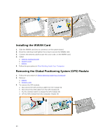
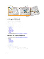
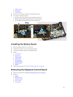
Installing the Card Bracket 1. Place the card bracket in the slot on the computer chassis. 2. Connect the camera cable to the connector on the card bracket. 3. Flip the card bracket and seat the card on the slot. 4. Tighten the screws to secure the card bracket. 5. Route the GPS and the C-storage cable through the routing channels. 6. Connect the MEMS cables to the system board. 7. Connect the battery cable to the battery board connector and the system board. 8. Install: a. hard drive b. MEMS board c. USH board d. GPS module e. hard drive f. bottom cover g. battery 9. Follow the procedures in After Working Inside Your Computer. Removing the I/O Board 1. Follow the procedures in Before Working Inside Your Computer. 2. Remove: a. battery b. bottom cover c. docking board d. GPS module e. USH board f. MEMS board g. hard drive h. Disconnect the battery cable from the battery board. i. card bracket 3. To remove the I/O board: a. Disconnect the cable from the I/O board [1,2]. b. Remove the screws that secure the I/O board [3]. c. Lift the I/O board from the slot [4]. 27
-
 1
1 -
2
-
3
-
4
-
5
-
6
-
7
-
8
-
9
-
10
-
11
-
12
-
13
-
14
-
15
-
16
-
17
-
18
-
19
-
20
-
21
-
 22
22 -
 23
23 -
 24
24 -
 25
25 -
 26
26 -
 27
27 -
 28
28 -
 29
29 -
 30
30 -
 31
31 -
 32
32 -
33
-
34
-
35
-
36
-
37
-
38
-
39
-
40
-
41
-
42
-
43
-
44
-
45
-
46
-
47
-
48
-
49
-
50
-
51
-
52
-
53
-
54
-
55
-
56
-
57
-
58
 |
 |
