Dell Inspiron 15 Gaming 7577 Inspiron 15 7000 Gaming Service Manual - Page 51
Replacing the computer base, Procedure
 |
View all Dell Inspiron 15 Gaming 7577 manuals
Add to My Manuals
Save this manual to your list of manuals |
Page 51 highlights
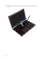
Replacing the computer base WARNING: Before working inside your computer, read the safety information that shipped with your computer and follow the steps in Before working inside your computer. After working inside your computer, follow the instructions in After working inside your computer. For more safety best practices, see the Regulatory Compliance home page at www.dell.com/ regulatory_compliance. Procedure 1 Replace the speakers. 2 Replace the status-light board. 3 Replace the power-adapter port. 4 Replace the system board. 5 Align and place the palm-rest assembly on the computer base. 6 Press down the edges of the palm-rest assembly and snap it into place. 7 Close the display and turn the computer over. 8 Replace the four screws (M2x3) that secure the computer base to the palm- rest assembly. 9 Replace the 19 screws (M2.5x6) that secure the computer base to the palm- rest assembly. 10 Slide the keyboard cable into the connector on the system board and close the latch to secure the cable. 11 Adhere the tape that secures the keyboard cable to the system board. 12 Slide the touchpad cable into the connector on the system board and close the latch to secure the cable. 13 Slide the keyboard-backlight cable into the connector on the system board and close the latch to secure the cable. 14 Slide the power-button board cable into the connector on the system board and close the latch to secure the cable. 15 Adhere the display cable to the computer base and route the display cable through the routing guides on the computer base. 16 Connect the display-cable to the system board. 51
-
 1
1 -
2
-
3
-
4
-
5
-
6
-
7
-
8
-
9
-
10
-
11
-
12
-
13
-
14
-
15
-
16
-
17
-
18
-
19
-
20
-
21
-
22
-
23
-
24
-
25
-
26
-
27
-
28
-
29
-
30
-
31
-
32
-
33
-
34
-
35
-
36
-
37
-
38
-
39
-
40
-
41
-
42
-
43
-
44
-
45
-
 46
46 -
 47
47 -
 48
48 -
 49
49 -
 50
50 -
 51
51 -
 52
52 -
 53
53 -
 54
54 -
 55
55 -
 56
56 -
57
-
58
-
59
-
60
-
61
-
62
-
63
-
64
-
65
-
66
-
67
-
68
-
69
-
70
-
71
-
72
-
73
-
74
-
75
-
76
-
77
-
78
-
79
-
80
-
81
-
82
-
83
-
84
-
85
-
86
-
87
-
88
-
89
-
90
-
91
-
92
-
93
-
94
-
95
-
96
-
97
-
98
-
99
-
100
-
101
-
102
-
103
-
104
-
105
-
106
-
107
-
108
-
109
-
110
-
111
-
112
-
113
-
114
-
115
-
116
-
117
-
118
-
119
-
120
-
121
-
122
-
123
-
124
-
125
-
126
-
127
-
128
-
129
-
130
-
131
-
132
-
133
-
134
-
135
-
136
-
137
-
138
-
139
-
140
-
141
-
142
-
143
 |
 |
