D-Link DFE-908X User Guide - Page 36
Crossover Cables
 |
UPC - 790069214066
View all D-Link DFE-908X manuals
Add to My Manuals
Save this manual to your list of manuals |
Page 36 highlights
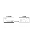
Contact 1 2 3 4 5 6 7 8 MDI-X Signal RD+ (receive) RD- (receive) TD+ (transmit) Not used Not used TD- (transmit) Not used Not used MDI Signal TD+ (transmit) TD- (transmit) RD+ (receive) Not used Not used RD- (receive) Not used Not used Crossover Cables When cascading or connecting the hub to another switch, bridge, or hub through the UTP port, a modified crossover cable is necessary. With a crossover cable, two pairs of wires are switched at one connector end. Carry out the following steps to create a customized, crossover twisted-pair cable: 1. Leave one end of the cable as is, with the RJ-45 connector intact. The wiring at just one end of the cable needs to be modified. 2. At the other end of the cable, connect wires 1 and 2 to contacts 3 and 6, respectively. Likewise, connect wires 3 and 6 to contacts 1 and 2. Refer to the following diagram: 24 Cables and Connectors
-
 1
1 -
2
-
3
-
4
-
5
-
6
-
7
-
8
-
9
-
10
-
11
-
12
-
13
-
14
-
15
-
16
-
17
-
18
-
19
-
20
-
21
-
22
-
23
-
24
-
25
-
26
-
27
-
28
-
29
-
30
-
 31
31 -
 32
32 -
 33
33 -
 34
34 -
 35
35 -
 36
36 -
 37
37 -
 38
38 -
 39
39 -
 40
40 -
 41
41 -
42
-
43
-
44
 |
 |
