D-Link DES-3550 Product Manual - Page 135
CPU Interface Filtering Rule Configuration, CPU Interface Filtering Rule Display for IP
 |
UPC - 790069266317
View all D-Link DES-3550 manuals
Add to My Manuals
Save this manual to your list of manuals |
Page 135 highlights
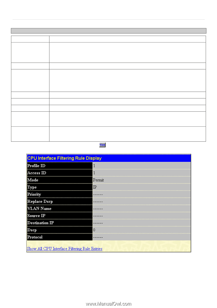
xStack® DES-3500 Series Layer 2 Stackable Fast Ethernet Managed Switch User Manual Configure the following CPU Interface Filtering Rule Configuration settings for IP: Parameter Description Profile ID Mode Access ID Type VLAN Name Source IP Destination IP Dscp (0-63) Protocol This is the identifier number for this profile set. Select Permit to specify that the packets that match the access profile are forwarded by the Switch, according to any additional rule added (see below). Select Deny to specify that packets that match the access profile are not forwarded by the Switch and will be filtered. Type in a unique identifier number for this access. This value can be set from 1 -65535. Selected profile based on Ethernet (MAC Address), IP address or Packet Content. • Ethernet instructs the Switch to examine the layer 2 part of each packet header. • IP instructs the Switch to examine the IP address in each frame's header. • Packet Content Mask instructs the Switch to examine the packet header. Allows the entry of a name for a previously configured VLAN. Source IP Address - Enter an IP Address mask for the source IP address. Destination IP Address- Enter an IP Address mask for the destination IP address. This field allows the user to enter a DSCP value in the space provided, which will instruct the Switch to examine the DiffServ Code part of each packet header and use this as the, or part of the criterion for forwarding. The user may choose a value between 0 and 63. This field allows the user to modify the protocol used to configure the CPU Interface Filtering Rule Table; depending on which protocol the user has chosen in the CPU Interface Filtering Profile Table. To view the settings of a previously configured rule, click screen: in the CPU Interface Filtering Rule Table to view the following Figure 6- 96. CPU Interface Filtering Rule Display for IP 120
-
 1
1 -
2
-
3
-
4
-
5
-
6
-
7
-
8
-
9
-
10
-
11
-
12
-
13
-
14
-
15
-
16
-
17
-
18
-
19
-
20
-
21
-
22
-
23
-
24
-
25
-
26
-
27
-
28
-
29
-
30
-
31
-
32
-
33
-
34
-
35
-
36
-
37
-
38
-
39
-
40
-
41
-
42
-
43
-
44
-
45
-
46
-
47
-
48
-
49
-
50
-
51
-
52
-
53
-
54
-
55
-
56
-
57
-
58
-
59
-
60
-
61
-
62
-
63
-
64
-
65
-
66
-
67
-
68
-
69
-
70
-
71
-
72
-
73
-
74
-
75
-
76
-
77
-
78
-
79
-
80
-
81
-
82
-
83
-
84
-
85
-
86
-
87
-
88
-
89
-
90
-
91
-
92
-
93
-
94
-
95
-
96
-
97
-
98
-
99
-
100
-
101
-
102
-
103
-
104
-
105
-
106
-
107
-
108
-
109
-
110
-
111
-
112
-
113
-
114
-
115
-
116
-
117
-
118
-
119
-
120
-
121
-
122
-
123
-
124
-
125
-
126
-
127
-
128
-
129
-
 130
130 -
 131
131 -
 132
132 -
 133
133 -
 134
134 -
 135
135 -
 136
136 -
 137
137 -
 138
138 -
 139
139 -
 140
140 -
141
-
142
-
143
-
144
-
145
-
146
-
147
-
148
-
149
-
150
-
151
-
152
-
153
-
154
-
155
-
156
-
157
-
158
-
159
-
160
-
161
-
162
-
163
-
164
-
165
-
166
-
167
-
168
-
169
-
170
-
171
-
172
-
173
-
174
-
175
-
176
-
177
-
178
-
179
-
180
-
181
-
182
-
183
-
184
-
185
-
186
-
187
-
188
-
189
-
190
-
191
-
192
-
193
-
194
-
195
-
196
-
197
-
198
-
199
-
200
-
201
-
202
-
203
-
204
-
205
-
206
-
207
-
208
-
209
-
210
-
211
-
212
-
213
-
214
-
215
-
216
-
217
-
218
-
219
-
220
-
221
-
222
-
223
-
224
-
225
-
226
-
227
-
228
-
229
-
230
-
231
-
232
-
233
-
234
-
235
-
236
-
237
-
238
-
239
-
240
-
241
-
242
-
243
-
244
-
245
-
246
-
247
-
248
-
249
-
250
-
251
-
252
-
253
-
254
-
255
-
256
-
257
-
258
-
259
-
260
-
261
-
262
-
263
-
264
-
265
-
266
-
267
-
268
-
269
-
270
-
271
-
272
-
273
-
274
-
275
-
276
-
277
-
278
-
279
-
280
-
281
-
282
-
283
-
284
-
285
-
286
-
287
-
288
-
289
-
290
-
291
-
292
-
293
-
294
-
295
-
296
-
297
-
298
-
299
-
300
-
301
-
302
-
303
-
304
-
305
-
306
-
307
-
308
-
309
-
310
-
311
-
312
-
313
-
314
-
315
-
316
-
317
-
318
-
319
-
320
-
321
-
322
-
323
-
324
-
325
-
326
-
327
-
328
 |
 |