D-Link DES-3010FA Product Manual - Page 244
Defining RMON Alarms, Viewing Statistics, RMON Alarm
 |
UPC - 790069280610
View all D-Link DES-3010FA manuals
Add to My Manuals
Save this manual to your list of manuals |
Page 244 highlights
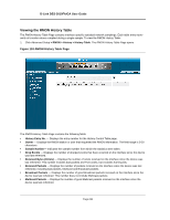
Viewing Statistics Managing RMON Statistics Defining RMON Alarms The RMON Alarm Page contains fields for setting network alarms. Network alarms occur when a network problem, or event, is detected. Rising and falling thresholds generate events. To set RMON alarms: 1. Click Advanced Setup > RMON > Alarm. The RMON Alarm Page opens. Figure 156:RMON Alarm Page The RMON Alarm Page contains the following fields: • Alarm Entry - Indicates a specific alarm. • Counter Name - Displays the selected MIB variable. • Interface - Displays interface for which RMON statistics are displayed. The possible field values are: - Port - Displays the RMON statistics for the selected port. - LAG - Displays the RMON statistics for the selected LAG. • Counter Value - Displays the selected MIB variable value. • Sample Type - Defines the sampling method for the selected variable and comparing the value against the thresholds. The possible field values are: - Delta - Subtracts the last sampled value from the current value. The difference in the values is compared to the threshold. - Absolute - Compares the values directly with the thresholds at the end of the sampling interval. • Rising Threshold - Displays the rising counter value that triggers the rising threshold alarm. The rising threshold is presented on top of the graph bars. Each monitored variable is designated a color. • Rising Event - Displays the mechanism in which the alarms are reported. The possible field values are: - LOG - Indicates there is not a saving mechanism for either the device or in the management system. If the device is not reset, the entry remains in the Log Table. - TRAP - Indicates that an SNMP trap is generated, and sent via the Trap mechanism. The Trap can also be saved using the Trap mechanism. - Both- Indicates that both the Log and Trap mechanism are used to report alarms. • Falling Threshold - Displays the falling counter value that triggers the falling threshold alarm. The falling threshold is graphically presented on top of the graph bars. Each monitored variable is designated a color. • Falling Event - Displays the mechanism in which the alarms are reported. Page 243
-
 1
1 -
2
-
3
-
4
-
5
-
6
-
7
-
8
-
9
-
10
-
11
-
12
-
13
-
14
-
15
-
16
-
17
-
18
-
19
-
20
-
21
-
22
-
23
-
24
-
25
-
26
-
27
-
28
-
29
-
30
-
31
-
32
-
33
-
34
-
35
-
36
-
37
-
38
-
39
-
40
-
41
-
42
-
43
-
44
-
45
-
46
-
47
-
48
-
49
-
50
-
51
-
52
-
53
-
54
-
55
-
56
-
57
-
58
-
59
-
60
-
61
-
62
-
63
-
64
-
65
-
66
-
67
-
68
-
69
-
70
-
71
-
72
-
73
-
74
-
75
-
76
-
77
-
78
-
79
-
80
-
81
-
82
-
83
-
84
-
85
-
86
-
87
-
88
-
89
-
90
-
91
-
92
-
93
-
94
-
95
-
96
-
97
-
98
-
99
-
100
-
101
-
102
-
103
-
104
-
105
-
106
-
107
-
108
-
109
-
110
-
111
-
112
-
113
-
114
-
115
-
116
-
117
-
118
-
119
-
120
-
121
-
122
-
123
-
124
-
125
-
126
-
127
-
128
-
129
-
130
-
131
-
132
-
133
-
134
-
135
-
136
-
137
-
138
-
139
-
140
-
141
-
142
-
143
-
144
-
145
-
146
-
147
-
148
-
149
-
150
-
151
-
152
-
153
-
154
-
155
-
156
-
157
-
158
-
159
-
160
-
161
-
162
-
163
-
164
-
165
-
166
-
167
-
168
-
169
-
170
-
171
-
172
-
173
-
174
-
175
-
176
-
177
-
178
-
179
-
180
-
181
-
182
-
183
-
184
-
185
-
186
-
187
-
188
-
189
-
190
-
191
-
192
-
193
-
194
-
195
-
196
-
197
-
198
-
199
-
200
-
201
-
202
-
203
-
204
-
205
-
206
-
207
-
208
-
209
-
210
-
211
-
212
-
213
-
214
-
215
-
216
-
217
-
218
-
219
-
220
-
221
-
222
-
223
-
224
-
225
-
226
-
227
-
228
-
229
-
230
-
231
-
232
-
233
-
234
-
235
-
236
-
237
-
238
-
 239
239 -
 240
240 -
 241
241 -
 242
242 -
 243
243 -
 244
244 -
 245
245 -
 246
246 -
 247
247 -
 248
248 -
 249
249 -
250
-
251
-
252
-
253
-
254
-
255
-
256
-
257
-
258
-
259
-
260
-
261
-
262
-
263
-
264
-
265
-
266
-
267
-
268
-
269
-
270
-
271
-
272
-
273
-
274
-
275
-
276
-
277
-
278
-
279
-
280
-
281
 |
 |
