D-Link DBG-2000 Quick Install Guide - Page 2
About This Guide, Unpacking the Product, Product Overview
 |
View all D-Link DBG-2000 manuals
Add to My Manuals
Save this manual to your list of manuals |
Page 2 highlights
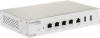
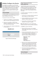
ENGLISH About This Guide This guide gives step by step instructions for setting up D-Link DBG-2000. Please note that the model you have purchased may appear slightly different from those shown in the illustrations. E USB Port (1) It can support various USB 2.0, 3.0 devices below: 1.Flash Disk or Hard Disk for network sharing. 2.Printer (It will be supported by future firmware upgrade) Table 1: DBG-2000 Front Panel Descriptions Unpacking the Product Open the shipping carton and carefully unpack its contents. Please consult the packing list located in following information to make sure all items are present and undamaged. If any item is missing or damaged, please contact your local D-Link reseller for replacement. - One (1) DBG-2000 One (1) 12V/2A Power Adapter - One (1) Console Cable (RJ45-to-DB9 Cable) - One (1) Ethernet (CAT5 UTP/Straight Through) Cable - Four (4) Rubber foot Product Overview This chapter provides detailed descriptions of the DBG-2000 device and its components. Front Panel A B C DE Figure 1. DBG-2000 Front Panel Item Feature Description A LED Power LED: Indicates the device is (Top to bottom) powered on. B Ethernet ports Connect Ethernet devices, such as (1-4) computers, switches and hubs. C Gigabit WAN port (2) Two auto MDI/MDIX WAN ports are the connection for the Ethernet cable to the cable or DSL modem. D Console Port (1) Used to access Command Line Interface (CLI) via RJ45-to-DB9 console Cable. 2 D-Link Nuclias Cloud Router Device Status LEDs and Ethernet Port LEDs Link Speed TX/RX Status Figure 2. Ethernet RJ-45 Port LEDs The device LEDs show information about current device status. When the device power up, the POWER/STATUS LED will show solid orange during power on process. Startup takes one minute approximately to complete, the LED will change to solid green. If you want to turn the device off and on again, we recommend you wait a few seconds between shutting it down and powering it back. The Ethernet LEDs show the status of each Ethernet port. Table 2 lists the name, color, status and description of each device LED. LED Indicative Power Color Orange/ Green Cloud Green/ Orange/ Red LAN RJ45 Phone Jack Green/ Amber WAN RJ45 Phone Jack Blue/ Green/ Amber Status Description Solid Orange Device during power-on process Solid Green Completion of power on Light Off The device is power-off Solid Orange Device is connecting to Cloud Solid Green Device is in Cloud mode Solid Red Device is not in Cloud mode Blinking Orange Device is upgrading firmware or resetting factory default Right Side Solid Amber 10/100Mbps Link Present Blinking Amber There is activity on this port Light Off No link Left Side Solid Green 1000Mbps Link Present Blinking Green There is activity on this port Light off No Link Right Side Solid Green 1000Mbps Link Present Solid Amber 10/100Mbps Link Present Blinking There is activity on this port Green/Amber Light Off No link Left Side Solid Blue 2.5Gbps Line Present Blinking Blue There is activity on this port Light Off No link Table 2: Device Status LED Descriptions
-
 1
1 -
 2
2 -
 3
3 -
 4
4 -
 5
5
 |
 |
