Cub Cadet 3X 26 inch TRAC Operation Manual - Page 9
Overhead Chute Rotation Control w/ 2-Way, Pitch, or 4-Way Pitch & Rotation Control
 |
View all Cub Cadet 3X 26 inch TRAC manuals
Add to My Manuals
Save this manual to your list of manuals |
Page 9 highlights
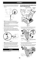
ASSEMBLY Overhead Chute Rotation Control w/ 2-Way Pitch or 4-Way Pitch & Rotation Control Chute Control Rod 2 Way/4 Way Control 3. Place chute assembly onto chute base and ensure chute control rod is positioned above lower handle. Install hex screw (c) removed in Step 1, but do not secure with wing nut at this time (Figure 15). c Chute Assembly Figure 12 1. Remove hairpin clip (a), wing nut (b) and hex screw (c) from chute control head and clevis pin (d) and bow-tie cotter pin (e) from chute support bracket (Figure 13). Chute Control Head c a Chute Support d Bracket b e Chute Assembly Chute Base 21 Figure 13 NOTE: For smoothest operation, cables should all be to the left of the chute control rod. 2. Insert chute control rod into chute control head. Push rod as far into chute control head as possible, keeping holes in rod pointing upward (Figure 14). Figure 15 4. Squeeze trigger on 2-way/4-way chute control and rotate chute by hand to face forward. The holes in chute control collar will be facing up (Figure 16). Chute Control Collar Top View 2-Way/4-Way Chute Control (One O'clock Position) Figure 16 IMPORTANT: Chute will not rotate without squeezing trigger on 2-way/4-way chute control. 5. Rotate 2-way/4-way chute control to one o'clock position (Figure 16) so that indicator arrow on pinion gear below control handle faces upward (Figure 17). Figure 14 Figure 17 9
-
 1
1 -
2
-
3
-
 4
4 -
 5
5 -
 6
6 -
 7
7 -
 8
8 -
 9
9 -
 10
10 -
 11
11 -
 12
12 -
 13
13 -
 14
14 -
15
-
16
-
17
-
18
-
19
-
20
-
21
-
22
-
23
-
24
-
25
-
26
-
27
-
28
-
29
-
30
-
31
-
32
-
33
-
34
-
35
-
36
-
37
-
38
-
39
-
40
-
41
-
42
-
43
-
44
-
45
-
46
-
47
-
48
-
49
-
50
-
51
-
52
-
53
-
54
-
55
-
56
-
57
-
58
-
59
-
60
-
61
-
62
-
63
-
64
-
65
-
66
-
67
-
68
-
69
-
70
-
71
-
72
-
73
-
74
-
75
-
76
-
77
-
78
-
79
-
80
 |
 |
