Cobra PRO 2500W PRO 2500W Manual - Page 13
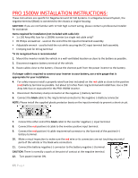
Pro 1500w Installation Instructions
 |
View all Cobra PRO 2500W manuals
Add to My Manuals
Save this manual to your list of manuals |
Page 13 highlights
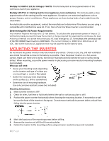
PRO 1500W INSTALLATION INSTRUCTIONS: These instructions are specific for Negative Ground 12 Volt Systems. In a Negative Ground System, the negative terminal (Black) is connected to the chassis or engine housing. CAUTION: If you are not familiar with 12 Volt high current wiring, please contact a professional installer for assistance. Items required for installation (not included with cable kit): • 1 x 150 Amp ANL fuse for a 1500W inverter (on single red cable only)* • #2 Philips screwdriver - used on the end of the DC input terminal bolt assembly • Adjustable wrench - used to hold the nut while securing the DC input terminal bolt assembly • Crimping tool for #2 lug terminal *A UL recognized fuse is recommended 1. Mount the inverter inside the vehicle in a well ventilated location as close to the battery as possible. 2. Disconnect negative battery terminal of the vehicle. 3. Route cables close to the battery. Choose the shortest path from the power inverter to the battery. If a longer cable is required to connect your inverter to your battery, use a wire gauge that is appropriate for your installation. 4. For safety reasons install a properly rated fuse (not included) on the red cable as close to the positive (red) battery terminal as possible. Cut about 12 inches from ring terminal and install fuse. Use a 150 Amp ANL fuse or equivalent for the PRO 1500W inverter. 5. Disconnect the battery clamp connector at the negative (-) battery terminal. 6. Connect the black cable to the ring terminal connector to the negative (-) battery connector. NOTE: Please install the supplied plastic protector boots on the input terminals to prevent a short circuit. 7. Connect the other end of the black cable to the inverter negative (-) input terminal. 8. Connect the red positive (+) cable to the inverter positive input terminal. 9. Connect the red positive (+) cable ring terminal connector to the fuse end of the positive (+) battery terminal. 10. Make a visual inspection to make sure the red wire or its connectors are not touching any metal parts of the vehicle or the black wire connectors. 11. Connect the battery negative (-) connector to the battery negative (-) terminal. CAUTION: There is normally a spark at the point of contact at the negative terminal. 12. Turn power inverter ON. 13 | P a g e
-
 1
1 -
2
-
3
-
4
-
5
-
6
-
7
-
 8
8 -
 9
9 -
 10
10 -
 11
11 -
 12
12 -
 13
13 -
 14
14 -
 15
15 -
 16
16 -
 17
17 -
 18
18 -
19
-
20
-
21
-
22
-
23
-
24
-
25
-
26
-
27
-
28
-
29
-
30
-
31
-
32
-
33
-
34
 |
 |
