Cobra CPI 2590 CPI 2590 - English - Page 5
Quick Evaluation, Before Installation
 |
View all Cobra CPI 2590 manuals
Add to My Manuals
Save this manual to your list of manuals |
Page 5 highlights
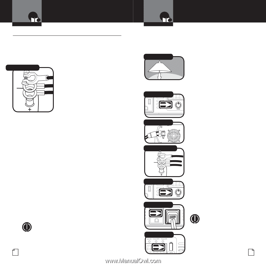
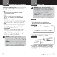
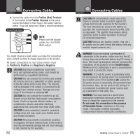
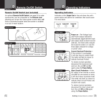
Introduction Quick Evaluation Before Installation Quick EvInatroluatioOnperaBtioen foreCAsuIssnitsotmsanetcreallatiWoanrranty • This section provides you with basic information about the inverter and how to check its performance before installation. Be sure to have on hand: 1. A 12 volt DC Installation power source (such as a vNeothesicle battery). Secondary Icons Connect Power Source The power source must provide between 11 and 15 volts DC and be able to supply enough current to run the test load. As a rough guide, Noticdeivide thCeauwtioanttage oWf atrhneingtest load by 10 to get the current (in amperes) the power source must deliver. 2. Cables to connect the power source to the inverter (not included). The cables must be as short and thick as possible in order to reduce the voltage drop between the power source and the inverter when it is drawing current from the power source. If the cable suffers an excessive voltage drop, the inverter ain Icons may shut down when drawing higher currents because the voltage at the inverter dropped below 10 volts. #4 AWG stranded copper cable is recommended. It should be no longer than four feet (one and one-half meters). Intro Operation Customer Warranty The other end of Assistancethe cable, which connects to the power source, must be terminated with a lug or other connector that provides a secure, low resistance connection. econdary Icons FIonsrtalleatxionample, if the poNwotees r source is a battery, the cable must be terminated with a battery terminal that clamps to the post on the battery. NOTE Use double cables for a full 2500 Watt load. Notice Caution Warning 4 Introduction Quick Evaluation Before Installation 3. A teMsaint load IconInstro that cOapnerabtioen pluggACesussditsotmainnectreo the WAaCrrarnetyceptacle on the inverter for short term testing at a low power level. The following cables are recommended for testing low power level test loads only. Test Load Intro Secondary Icons Test Installation Load Operation PowCuestromer Assistance 100W 250W 500W NMotiens imum WarCraantyble Size # 16 AWG copper # 12 AWG copper # 8 AWG copper To check your Installation inverteNr'osticeperformCaaunticone befNootreesWairnnisngtallation: Power BSuetctoonndary Icons 1. Turn the inverter off (see page 14 for details). If the power source is a DC power supply, switch it off as well. Main Icons Connect Terminals 2. Notice ConnCaeuctiotn cablesWtaorninpgower input terminals (see page 8 for details). 3. Connect cables to power source (see page 8 for details). Main Icons 4. Check to make sure all Connect PowerInMStraooinuIrcocnes Operation conCnusetocmteior ns arWearsraentcyure. 5. TurAnsstishtaenceinverter on. If the power source is a DC power supply, switch it on first. Intro Main Icons 6. Plug in the test load. Operation Customer InstallatioAnssistance Warranty Notes Intro Power BSuetctoonndary Icons TOhpeeratiionn verteCArsusssitsohtmanoecreuld suWparpranlyty power to the load. If the inverter is not Installation working properly, refer to the troubleshooNtoitnesg guide on page 20 Installation or power and protection indicators Secondary Icons section on page 16. Connect ITnterost Load OperationNotice Secondary Icons CustomeCr aution Assistance Notes WarrantWy arning USSeBcoOnduartyleIctons Notice Installation Caution Notice NOTE A USB device can be usedWatrnoingcheck the output of the USB CaNutoiotens OuWtarlneintg. Notice Nothing Comes Close to a Cobra™ 5 Caution Warning
-
 1
1 -
 2
2 -
 3
3 -
 4
4 -
 5
5 -
 6
6 -
 7
7 -
 8
8 -
 9
9 -
 10
10 -
 11
11 -
12
-
13
-
14
-
15
 |
 |