Carvin SLP5600 Instruction Manual - Page 10
Standard Live, Master
 |
View all Carvin SLP5600 manuals
Add to My Manuals
Save this manual to your list of manuals |
Page 10 highlights
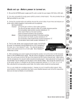
18. CHANNEL AUX 3 AND AUX 4 PRE OR POST SENDS The AUX 3 and AUX 4 level controls (with the Aux 3 - 4 PRE switch in) provides a total of 4 PRE monitor controls when used with AUX 1 and AUX 2 (4 monitor mixes). With the Aux 3 - 4 PRE switch out, AUX 3 and AUX 4 can be used with AUX 5 and AUX 6 as effects sends for a total of 4 post sends. 19. TAPE 5 - 6 SWITCH The TAPE 5 - 6 switch is linked to the TAPE switch at the top of the channel. Here the alternate input (the input not going to the fader) can be sourced to AUX 5 and AUX 6. This is used primarily in recording during tracking to provide playback to the studio musicians. 20. CHANNEL AUX 5 AND AUX 6 POST SENDS The AUX 5 and AUX 6 sends are post EQ and post Fader sends when the TAPE 5-6 switch is up. The AUX 5 and AUX 6 sends are designed for effects sends or any other fader tracking sends needed. See Tape 5-6 switch for it's tape input effects on AUX 5 and AUX 6. 21. CHANNEL AUX 7/8 TAPE SWITCH The 7/8 TAPE switch is linked to the TAPE switch at the top of the channel. Here the alternate input (the input not going to the fader) can be sourced to the stereo pair of AUX 7 and AUX 8. This is used primarily in recording during tracking to provide playback mixing for the control room and to the studio musicians. 22. CHANNEL AUX 7/8 PRE FAD W/ EQ SWITCH The PRE FAD w/ EQ switch in the up position places the stereo pair of AUX 7 and AUX 8 controls post EQ and post fader for use as effects sends. In the down position, the stereo pair of AUX 7 and AUX 8 controls are post EQ, pre mute and pre fader for stereo in-ear monitor sends or a stereo drum monitor send. This switch only works when the AUX 7/8 TAPE switch is in the up position. 5 AUX 23. CHANNEL AUX 7-8 PRE OR POST STEREO SENDS The stereo pair of AUX 7 and AUX 8 level controls are post EQ and post fader sends when the TAPE and PRE FAD w/ EQ switches are up. The stereo pair is made up of the 7/8 level control and the 7/8 pan control which pans between the two send AUX 7 and AUX 8. The stereo pair of AUX 7 and AUX 8 sends are designed for effects sends or any other fader tracking send needed. 0 1 10 PRE 1-2 5 5 0 2 10 See TAPE switch for its tape input effects on AUX 7 and AUX 8. 3 24. PAN 0 10 4 5 18 This is the channel's main PAN control. It allows the channel's signal to be place anywhere in the stereo field from left to right PRE 3- 4 0 10 with the center detent being centered. The PAN control in the studio is typically used for adjusting the stereo field for each 5 5 channel, but it is also used for assigning channels to individual buses. The later is typical for live mixing where certain chan- 0 10 6 nels are grouped to a single bus for sub group mixing. See Standard Live mixer set-ups for more details on sub mixing. 19 5 20 25. PEAK, SOLO, AND MUTE INDICATORS The RED PEAK LED indicator is pre-fader and post EQ. A constantly lit LED indicates the signal probably needs a reduction TAPE 5 - 6 0 10 7/8 5 TAPE 21 in the GAIN control to prevent input overloading. The GREEN SOLO LED indicates the solo switch has been pressed on the channel. The RED MUTE LED indicates the MUTE switch has been pressed on the channel. 23 0 10 C 22 26. MUTE SWITCH PRE FAD w/EQ 7 PAN 8 The MUTE switch turns off the channel at the fader. All sends which are pre fader will not be muted. This is extremely useful C when you need to mute channels but can't afford to lose fader settings. 24 27. SOLO SWITCH The SOLO switch allows the operator to monitor each channel. The SOLO switch can be set for either "PFL mode" (Pre Fader Listen) or "SOLO after fader" where the channel's pan position is heard when soloed. The switch to change the SOLO mode is found in the CONTROL MASTERS section of the console. See Master Section for more information. 28. ASSIGNMENT SWITCHES These switches assign the channels' signal to the group faders (8 buses) for sub-mixing and to the Left & Right faders in the Master Section. Each channel can be assigned to the 1-2, 3-4, 5-6, 7-8, and L-R Faders in stereo pairs. This feature allows the operator to group certain channels (such as the channels used to mic an entire drum kit) and assign them to one pair of the master faders in the 1-2, 3-4 sub group. This sub-mixing feature decreases the number of channel faders that need to be adjusted. See Standard Live mixer setups for more details on sub mixing. LR PAN PK SOLO 25 MUTE +12 26 SOLO + 9 27 +6 1-2 + 3 3-4 0 3 5-6 6 7-8 28 29. CHANNEL FADER The channel FADER control is the final level control of the channel before the PAN control. The Fader has a 0dB marker for nominal setting of the channel. For typical mixing the 0dB position provides the lowest noise and highest headroom for the channel. The Fader has an added 12dB of gain for signals that need an extra boost in the mix, however pushing the fader above the 0db marker should be done in moderation. The channels have plenty of headroom but the proper adjustment should be made at the channel's input or GAIN control. Be aware of the signals and fader settings so you don't over-drive the bus or degrading the channel's signal by over-driving the faders. The meter bridge and direct outputs are sourced after the fader. 12 L-R 18 24 30 40 50 oo 29 10
-
 1
1 -
2
-
3
-
4
-
 5
5 -
 6
6 -
 7
7 -
 8
8 -
 9
9 -
 10
10 -
 11
11 -
 12
12 -
 13
13 -
 14
14 -
 15
15 -
16
-
17
-
18
-
19
-
20
-
21
-
22
-
23
-
24
-
25
-
26
-
27
-
28
-
29
-
30
-
31
-
32
-
33
-
34
-
35
-
36
-
37
-
38
 |
 |
