Boss Audio BE2000.1D User Manual - Page 4
LTT Lr
 |
View all Boss Audio BE2000.1D manuals
Add to My Manuals
Save this manual to your list of manuals |
Page 4 highlights
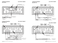
Features Your new ELITE amplifier features the following: • Class D Topology • Bridgeable outputs (Except BE1200.1D) • MOSFET PWM (Pulse Width Modulated) Power Supply • 2O stable stereo operation with output power increase (1Ostable for BE1200.1D) • Thermal and speaker short protection • Soft turn-on circuit • Remote turn-on/turn-off circuit • Variable input gain control • Variable low pass filter • Variable high pass filter (Except BE1200.1D) • Variable Subsonic filter (BE1200.1D) • Variable 0 to + 12dB Bass Boost • RCA WIRE low level inputs • LED power and protection indicators • Black anodized heatsink • Remote subwoofer control (BE1200.1D /BE2200.5D) • ILLUMINATED end panels About 2 O operation Your BOSS amplifier has been designed to operate efficiently at loads down to 2 O. (BE1200.1D down to 1O) When operating at 2O, the amplifiers will increase their output power by approximately 50%. The current draw will also increase by about the same amount, so be sure you have enough current to run the amplifiers into a 20 load. Before installing any electrical accessories to your vehicle, always make sure the vehicles electric system is equipped to handle the extra electrical load. Es_Fr MOSFET Amplifier User's Manual-page 3 Power and Speaker Wiring unannei ana esnagea moues 5-Channel Amplifier BE2200.5D Subwoofer SPEAKER IMPEDANCE 2-8 0 BROWN BROWN/BLACK Connect the Negative Hterminalof the subwoofer to the CH5()amplifier terminal. Connect the Negative (-) terminal of the subwoofer to the CH5(-) amplifier terminal. Bridged Mode OUTPUT CH7 00130 L.... O CH4 © MONO OUTPUT PWR 0 CH5 0 gum TT O PROT. (RED) r ID MS 0 R9SrNsEMs CLASS D 5-CH +12I/DC REM GROUND O O O0 POWER CE e1 GO® LEFT Subwoofer WHITE GRAY/BLACK O0 0 Chassis ground point RIGHT Ir rj GREEN Subwoofer PURPLE /BLACK SPEAKER IMPEDANCE 4-80 Connect the Positive (+) terminal of the LEFT subwoofer to the CHI (+) amplifier terminal. Connect the Negative (-) terminal of the LEFT subwoofer to the CH2 (-) amplifier terminal. Connect the Positive (+) terminal of the RIGHT subwoofer to the CH3 (+) amplifier terminal. Connect the Negative (-) terminal of the RIGHT subwoofer to the CH4 (-) amplifier terminal. to REMOTE TURN-ON terminal of head unit L-El FUSE O Battery Power and Speaker Wiring Full Range Monoblock Mode Full Range Monoblock Amplifier BE1200.1D Speaker MONO PWR OUTPUT (BLUE) r0 PZ( i r EFUSES .12 YDC O REM O GROUND O 1.9k): O O CLASS D MONOBLOCK CE8 GRAY GRAY/BLACK SPEAKER IMPEDANCE 1-B 0 GO® • O 0 J_ Chassis ground point .--- to REMOTE TURN-ON terminal of head unit O FUSE Battery ELITE MOSFETAmplifier User's Manual-page 16
-
 1
1 -
 2
2 -
 3
3 -
 4
4 -
 5
5 -
 6
6 -
 7
7 -
 8
8 -
 9
9 -
 10
10
 |
 |
