Avanti BCF54S3S Instruction Manual - Page 9
Installation Instructions
 |
View all Avanti BCF54S3S manuals
Add to My Manuals
Save this manual to your list of manuals |
Page 9 highlights
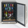
INSTALLATION INSTRUCTIONS BEFORE USING YOUR BEVERAGE COOLER • Remove the exterior and interior packing. • Check to be sure you have all of the following parts: 1 Instruction Manual 3 Beverage Shelves (2 Wire shelves / 1 Glass shelf) 1 Wooden Shelf with 90% pull-out assembly 2 Keys 1 Set Stainless Steel Hinges for Door Swing Reversal 2 Hinge Screw caps 1 Stainless Steel Handle • Before connecting this appliance to the power source, let it stand upright for approximately 2 hours. This will reduce the possibility of a malfunction in the cooling system from handling during transportation. • Clean the interior surface with lukewarm water using a soft cloth. INSTALLATION OF YOUR BEVERAGE COOLER • This appliance is designed to be for free standing installation or built-in (fully recessed). • Place your Beverage Cooler on a floor that is strong enough to support it when it is fully loaded. To level your Beverage Cooler, adjust the front leveling legs at the bottom of the Beverage Cooler. • Locate the Beverage Cooler away from direct sunlight and sources of heat (stove, heater, radiator, etc.). Direct sunlight may affect the acrylic coating and heat sources may increase electrical consumption. Extreme cold ambient temperatures may also cause the unit not to perform properly. • Avoid locating the unit in moist areas. • Plug the Beverage Cooler into an exclusive, properly installed-grounded wall outlet. Do not under any circumstances cut or remove the third (ground) prong from the power cord. Any questions concerning power and/or grounding should be directed toward a certified electrician or an authorized Avanti Products service center. BUILT - IN CABINET INSTRUCTIONS This unit is designed for both built-in or free standing installation. If you plan to use this unit in a built-in application please follow the requirements shown to the right. ← Figure shown Cabinet Opening Dimensions IN (min) MM (min) Width 24" 610 mm Depth 26" 661 mm Height 35" 889 mm → Figure shown Unit Dimensions IN (min) MM (min) Width Depth (with handle) Depth (without handle) Height 23 1/2" 25 1/4" 23 1/2" 33 3/4" 597 mm 641 mm 597 mm 857 mm 9
-
 1
1 -
2
-
3
-
 4
4 -
 5
5 -
 6
6 -
 7
7 -
 8
8 -
 9
9 -
 10
10 -
 11
11 -
 12
12 -
 13
13 -
 14
14 -
15
-
16
-
17
-
18
-
19
-
20
 |
 |
