Adaptec 5805 User Guide
Adaptec 5805 - RAID Controller Manual
 |
UPC - 760884154496
View all Adaptec 5805 manuals
Add to My Manuals
Save this manual to your list of manuals |
Adaptec 5805 manual content summary:
- Adaptec 5805 | User Guide - Page 1
Serial Attached SCSI RAID Controllers Installation and User's Guide - Adaptec 5805 | User Guide - Page 2
Adaptec, Adaptec Storage Manager, MaxIQ, SerialSelect, and the Adaptec logo are trademarks of Adaptec, Inc., which may be registered in some jurisdictions. Microsoft, Windows . Adaptec reserves the right to make changes in the product design without reservation and without notification to its users. - Adaptec 5805 | User Guide - Page 3
installing or using your Adaptec product, check this document first-you will find answers to most of your questions. If you need further assistance, use the support options listed below. To expedite your service, have your computer in front of you. Technical Support Identification (TSID) Number - Adaptec 5805 | User Guide - Page 4
, at its option, will repair or replace the product, or refund the purchaser's purchase price for the product, provided it is delivered at the purchaser's expense to an authorized Adaptec service facility or to Adaptec. 2. Repair or replacement parts or products will be furnished on an exchange - Adaptec 5805 | User Guide - Page 5
the listed ITE: Adaptec RAID 5085/Adaptec RAID 5405/Adaptec RAID 5445/ Adaptec RAID 5805/ Adaptec RAID 5405Z/Adaptec RAID 5805Z/Adaptec RAID 5445Z/ Adaptec RAID 5805Q/Adaptec RAID 5805ZQ/ Adaptec RAID 51245/Adaptec RAID 51645/Adaptec RAID 52445/ Adaptec RAID 2045/Adaptec RAID 2405/Adaptec RAID 2405Q - Adaptec 5805 | User Guide - Page 6
a Battery Backup Module 17 Upgrading the Controller Firmware 17 About the Adaptec RAID 5085 18 About the Adaptec RAID 5405 19 About the Adaptec RAID 5445 20 About the Adaptec RAID 5805/5805Q 21 About the Adaptec RAID 51245 22 About the Adaptec RAID 51645 23 About the Adaptec RAID 52445 - Adaptec 5805 | User Guide - Page 7
a System Backplane 39 Connecting MaxIQ Solid State Drives and other SSDs 40 Connecting External Devices 42 Next Steps ...42 Creating a Bootable Array Setting the Boot Controller 44 Creating an Array 44 Creating an Array with the ACU 44 Creating an Array with Adaptec Storage Manager 46 Making - Adaptec 5805 | User Guide - Page 8
Storage Manager 60 About the Adaptec RAID Controller Configuration Utility 60 About the Adaptec RAID Configuration Utility 61 About the Adaptec Flash Utility 61 Which Utility Should I Use 61 Solving Problems Troubleshooting Checklist 63 Monitoring Disk Drives Status 63 Silencing the Alarm - Adaptec 5805 | User Guide - Page 9
Existing Arrays 85 Initializing Disk Drives 86 Rescanning Disk Drives 86 Secure Erasing Disk Drives 87 Managing Global Hot Spares 87 Using the ACU to Create and Manage JBODs 87 Creating a New JBOD 87 Managing Existing JBODs 88 Using the ACU to Manage the MaxIQ Pool 88 Using SerialSelect - Adaptec 5805 | User Guide - Page 10
105 Obtaining the Firmware 105 Creating the Firmware Update Disks 106 Running the Menu-based AFU 106 Running the AFU from the Command Line 107 AFU Commands 107 Updating the Flash Using the AFU Command Line 110 Controller LED and I2C Connector Quick Reference Adaptec RAID 5085 LED Connector - Adaptec 5805 | User Guide - Page 11
(SAS) and Redundant Array of Independent Disk (RAID) technology. These RAID controller models are described in this guide: ● Adaptec RAID 5085 ● Adaptec RAID 5405/5405Z ● Adaptec RAID 5445/5445Z ● Adaptec RAID 5805/5805Q/5805Z/5805ZQ ● Adaptec RAID 51245 ● Adaptec RAID 51645 ● Adaptec RAID 52445 - Adaptec 5805 | User Guide - Page 12
the Adaptec Storage Manager software; accessible from the main window of Adaptec Storage Manager. ● Adaptec RAID Controller Command Line Utility User's Guide-Describes how to use the included Adaptec RAID Controller Configuration (ARCCONF) command line utility (see page 60) to perform basic array - Adaptec 5805 | User Guide - Page 13
Kit Contents and System Requirements 2 In this chapter... Kit Contents...14 System Requirements ...14 This chapter lists the contents of your Adaptec RAID controller kit and the system requirements that must be met for you to successfully install and use your controller. - Adaptec 5805 | User Guide - Page 14
of Linux or to download driver sources, visit the Support area of the Adaptec Web site at www.adaptec.com. ● SCO® OpenServer® 6.0 MP4 ● UnixWare® 7.1.4 ● Sun® SolarisTM 10, Solaris 10 x86 U7, Solaris 10 x64 U4 ● VMware ESX Server 3.5 with U1, U2, or U3, VMware ESX Server 4.0 (storage management must - Adaptec 5805 | User Guide - Page 15
Standard RAID Controller Features 16 Adding a Battery Backup Module 17 Upgrading the Controller Firmware 17 About the Adaptec RAID 5085 18 About the Adaptec RAID 5405 19 About the Adaptec RAID 5445 20 About the Adaptec RAID 5805/5805Q 21 About the Adaptec RAID 51245 22 About the Adaptec RAID - Adaptec 5805 | User Guide - Page 16
updates to controller firmware, BIOS, and the Adaptec RAID Configuration utility ● Disk drive hot-swapping ● Event logging and broadcasting including email and SNMP messages ● Multiple options for creating and managing RAID arrays-A full software application (Adaptec Storage Manager), a BIOS-based - Adaptec 5805 | User Guide - Page 17
com. Upgrading the Controller Firmware To upgrade the firmware on your Adaptec RAID controller, follow the instructions in Using the Adaptec Flash Utility on page 104. You can also use the Adaptec Storage Manager to upgrade your controller firmware, refer to the Adaptec Storage Manager User's Guide. - Adaptec 5805 | User Guide - Page 18
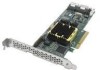
the Adaptec RAID 5085 The Adaptec RAID 5085 is a SAS RAID controller with these features: Ext. Alarm Aggregate Activity Mode 0 Flash connector Activity LEDs Diagnostic LEDs Audible Alarm Drive Activity LED connectors for CN1/CN0 CN0 CN1 2 external SAS connectors Mounting bracket Battery - Adaptec 5805 | User Guide - Page 19
) Standard cache Connectors, internal Maximum number of disk drives Enclosure Support Onboard speaker Battery Backup Module Low-profile MD2 PCIe x8 2.5 Gb/s 4 256 MB DDR2 1 mini-SAS x4 (SFF-8087) 4 direct-attached (or up to 256 with expanders) I2C and SGPIO Yes Adaptec Battery Module 800/800T (sold - Adaptec 5805 | User Guide - Page 20
3: About Your RAID Controller ● 20 About the Adaptec RAID 5445 The Adaptec RAID 5445 is a SAS RAID controller with these features: Drive Activity CN1/CN0 Status CN1/CN0 Mode 0 Flash connector Ext. Alarm External miniSAS connector CN1 Diagnostic LEDs (back of card) Internal mini-SAS connector CN0 - Adaptec 5805 | User Guide - Page 21
MB DDR2 2 mini-SAS x4 (SFF-8087) 8 direct-attached (or up to 256 with expanders) 5805: 8 Adaptec MaxIQ-branded/Intel X25-E SSDs (2TB max) 5805Q: 8 MaxIQ-compatible SSDs using any Solid State Drive on compatibility list (2TB max); see www.adaptec.com/ compatibility I2C and SGPIO Yes Adaptec Battery - Adaptec 5805 | User Guide - Page 22
, Exteneral Maximum number of disk drives Enclosure Support Onboard speaker Battery Backup Module Full Height, Half Length PCIe x8 2.5 Gb/s 16 512 MB DDR2 3 mini-SAS x4 (SFF-8087) 1 mini-SAS x4 (SFF-8088) 16 direct-attached (or up to 256 with expanders) I2C and SGPIO Yes Adaptec Battery Module 800 - Adaptec 5805 | User Guide - Page 23
, Exteneral Maximum number of disk drives Enclosure Support Onboard speaker Battery Backup Module Full Height, Half Length PCIe x8 2.5 Gb/s 20 512 MB DDR2 4 mini-SAS x4 (SFF-8087) 1 mini-SAS x4 (SFF-8088) 20 direct-attached (or up to 256 with expanders) I2C and SGPIO Yes Adaptec Battery Module 800 - Adaptec 5805 | User Guide - Page 24
, Exteneral Maximum number of disk drives Enclosure Support Onboard speaker Battery Backup Module Full Height, Half Length PCIe x8 2.5 Gb/s 28 512 MB DDR2 6 mini-SAS x4 (SFF-8087) 1 mini-SAS x4 (SFF-8088) 28 direct-attached (or up to 256 with expanders) I2C and SGPIO Yes Adaptec Battery Module 800 - Adaptec 5805 | User Guide - Page 25
Chapter 3: About Your RAID Controller ● 25 About the Adaptec RAID 5405Z The Adaptec RAID 5405Z is a SAS RAID controller with these features: Drive Activity LED connectors for CN0 Drive Activity LEDs for CN0 I2C connector for CN0 Ext. Alarm connector Aggregate Activity Mode 0 Flash connector - Adaptec 5805 | User Guide - Page 26
Chapter 3: About Your RAID Controller ● 26 About the Adaptec RAID 5445Z The Adaptec RAID 5445Z is a SAS RAID controller with these features: Drive Activity LED connectors for CN0/CN1 Drive Activity LEDs for CN0/CN1 I2C connectors for CN0/CN1 Ext. Alarm connector Aggregate Activity Mode 0 Flash - Adaptec 5805 | User Guide - Page 27
512 MB DDR2 Connectors, internal 2 mini-SAS x4 (SFF-8087) Maximum number of disk drives 8 direct-attached (or up to 256 with expanders) MaxIQ SSD support 5805Z: 8 Adaptec MaxIQ-branded/Intel X25-E SSDs (2TB max) 5805ZQ: 8 MaxIQ-compatible SSDs using any Solid State Drive on compatibility list - Adaptec 5805 | User Guide - Page 28
bus speed Phys (Unified Serial Ports) Standard cache Connectors, external Maximum number of disk drives Enclosure Support Onboard speaker Battery Backup Module Low-profile MD2 PCIe x8 2.5 Gb/s 4 128 MB DDR2 1 mini-SAS x4 (SFF-8088) 4 direct-attached (or up to 128 with expanders) I2C and SGPIO No No - Adaptec 5805 | User Guide - Page 29
speaker Battery Backup Module Low-profile MD2 PCIe x8 2.5 Gb/s 4 128 MB DDR2 1 mini-SAS x4 (SFF-8087) 4 direct-attached (or up to 128 with expanders) 2405: 1 Adaptec MaxIQ-branded/Intel X25-E SSDs (80GB max) 2405Q: 1 MaxIQ-compatible SSD using any Solid State Drive on compatibility list (80GB - Adaptec 5805 | User Guide - Page 30
Options ...33 Basic Installation Steps...34 This chapter provides the basic information you need to set up your disk drives and arrays the way you want them. It also describes the options you have for installing your Adaptec controller and disk drives, and creating arrays for data storage. - Adaptec 5805 | User Guide - Page 31
Adaptec controller's physical features and the RAID levels that it supports (see Standard RAID Controller Features on page 16). ● RAID 0 (Non-redundant Array)-Stripes data across multiple disk drives. Improved performance but no redundancy (see page 75). ● RAID 1 Array-Created from two disk drives - Adaptec 5805 | User Guide - Page 32
Cables Disk Drives Your SAS controller supports SAS disk drives, SATA disk drives, SATA Solid State Drives (SSD), and Adaptec MaxIQ Solid State Drives. When selecting disk drives for your RAID array, ensure that all the disk drives have the same performance level. You can use different-sized disk - Adaptec 5805 | User Guide - Page 33
to four SATA disk drives. External mini-SAS to mini-SAS (SFF-8088 to SFF-8088)- Connects to a backplane or enclosure. Internal mini-SAS to mini-SAS (SFF-8087 to SFF-8087)- Connects to a backplane or enclosure. Cable connectors are keyed so that you can't insert them incorrectly. Adaptec recommends - Adaptec 5805 | User Guide - Page 34
, you can connect external disk drives as well (or instead). 2 Set the boot controller (see page 44). 3 Create a bootable array (see page 44). 4 Install your operating system and the controller driver (see page 48.) 5 Install Adaptec Storage Manager and begin to manage your data storage (see page 59 - Adaptec 5805 | User Guide - Page 35
Installing the Controller and Disk Drives 5 In this chapter... Before You Begin ...36 Installing the Controller...36 Connecting Disk Drives to Your Controllers 38 Connecting External Devices 42 Next Steps ...42 This chapter explains how to install your Adaptec RAID controller, and how to - Adaptec 5805 | User Guide - Page 36
for your arrays (see page 32). ● Ensure that you have the proper cables for your controller and disk drives (see page 32). ● If you are installing a low-profile RAID controller into a low-profile computer cabinet, replace the original full-height bracket with the low-profile bracket included in the - Adaptec 5805 | User Guide - Page 37
to an I2C connector on an internal backplane or enclosure, using an I2C cable. For more connection details, see About Your RAID Controller on page 15. 7 Prepare and install your internal disk drives, following the instructions in Connecting Disk Drives to Your Controllers on page 38. If you are not - Adaptec 5805 | User Guide - Page 38
on page 42. Connecting Disk Drives to Your Controllers You can connect SAS disk drives, SATA disk drives, SATA Solid State Drives (SSD), and Adaptec MaxIQ Solid State Drives to your SAS RAID controller. (See www.adaptec.com/ compatibility for a list of compatible disk drives.) There are no jumpers - Adaptec 5805 | User Guide - Page 39
(For more information about backplane and expander connections, see page 71.) 1 Connect one or more internal SAS or SATA disk drives to the backplane. (Refer to your system's documentation for more information.) 2 Use an internal SAS cable to connect the controller to the backplane, as shown in the - Adaptec 5805 | User Guide - Page 40
8087 to SFF-8087) External SAS cable connecting to a drive bay Disk drives or SSDs on backplane Controller connected to backplane with multi-lane cable (SFF-8484) 3 When all internal disk drives have been installed and connected, close your computer cabinet, reattach the power cord, then continue - Adaptec 5805 | User Guide - Page 41
controller with SAS cables (mini-SAS to SATA). In a backplane connection, use the appropriate cable for your backplane type (see page 39 for more about backplane connections). You can connect a maximum of eight MaxIQ-compatible SSDs to a controller. For RAID arrays, Adaptec RAID controllers support - Adaptec 5805 | User Guide - Page 42
disk drives or disk drive enclosures. Adaptec recommends using only Adaptec cables. For more information or to purchase cables, visit the Adaptec Web site at www.adaptec.com. Next Steps If you are installing the controller driver and an operating system onto a bootable array, continue with Creating - Adaptec 5805 | User Guide - Page 43
an Array ...44 Making Your Array Bootable 47 This chapter explains how to set your Adaptec controller to be the boot controller, and how to create a bootable array. Note: If you are completing a standard installation onto an existing operating system, you don't have to complete this task. Skip - Adaptec 5805 | User Guide - Page 44
. For instructions, refer to the Adaptec RAID Controller Command Line Utility User's Guide. You can use either tool, but the ACU utility is the quicker and easier tool for this task. Note: Adaptec recommends that you not combine SAS and SATA disk drives within the same array. Adaptec Storage Manager - Adaptec 5805 | User Guide - Page 45
for each selected disk drive, then press Enter. 9 When the Array Properties screen opens, follow the instructions in the following table. Property Line Array Type Array Label Array Size Stripe Size Read Caching Write Caching Create RAID via [Done] Entry or Selection Select RAID 5, then press Enter - Adaptec 5805 | User Guide - Page 46
the Adaptec Storage Manager configuration wizard to build a RAID 5 array. Note: You will need the Adaptec RAID Controller Installation DVD to complete this task. To create a RAID 5 array: 1 Insert the Adaptec RAID Controller Installation DVD into your DVD drive, then restart your computer. 2 When - Adaptec 5805 | User Guide - Page 47
to store data. 10 Close all windows, then click Reboot to restart your system. 11 Remove the Adaptec RAID Controller Installation DVD. For information on installing and using Adaptec Storage Manager as a full software application, refer to the Adaptec Storage Manager User's Guide or online Help. 12 - Adaptec 5805 | User Guide - Page 48
You Begin ...49 Creating a Driver Disk ...49 Installing with Windows ...50 Installing with Red Hat Linux 51 Installing with SUSE Linux...51 Installing with OpenServer ...51 Installing with UnixWare ...52 Installing with Solaris...52 Installing with VMware ...53 Installing with FreeBSD ...53 This - Adaptec 5805 | User Guide - Page 49
2008, and Windows 7. To create a driver disk: 1 Set your system BIOS so that your computer boots from the DVD drive. (For instructions, refer to your computer documentation.) 2 Turn on your computer, then insert the RAID Controller Installation DVD included in your RAID controller kit. 3 Click - Adaptec 5805 | User Guide - Page 50
computer reads the disk. 6 When the Adaptec driver is found, press Enter. 7 Follow the on-screen instructions to complete the installation. 8 Continue with Managing Your Storage Space on page 59. Installing with Windows Server 2008, Windows 7, or Windows Vista To install the Adaptec RAID controller - Adaptec 5805 | User Guide - Page 51
, following the instructions included with your operating system. 8 Continue with Managing Your Storage Space on page 59. Installing with SUSE Linux To install the Adaptec RAID controller driver while installing SUSE Linux: 1 Insert the first SUSE Installation CD. 2 Restart your computer. 3 When the - Adaptec 5805 | User Guide - Page 52
the instructions included with your operating system. 7 Continue with Managing Your Storage Space on page 59. Installing with Solaris Note: This task is not necessary if you are installing Solaris 10 Update 2 or later. Instead, you can choose to install Solaris using the in-box driver and update it - Adaptec 5805 | User Guide - Page 53
the VMware installation. Note: The VMware embedded driver will see the device and install. 4 Complete the VMware installation, following the instructions included with your operating system. Note: Currently, the Adaptec Storage Manager GUI is not supported on VMware. To create and manage arrays - Adaptec 5805 | User Guide - Page 54
Driver Disk ...55 Installing on Windows ...56 Installing on Red Hat or SUSE Linux 56 Installing on OpenServer ...57 Installing on UnixWare ...57 Installing on Solaris...57 Installing on VMware...58 Installing on FreeBSD ...58 This chapter explains how to install your Adaptec RAID controller driver - Adaptec 5805 | User Guide - Page 55
OS support to generate a list of supported operating systems and to download the latest drivers. Creating a Driver Disk Note: You will need a floppy disk to complete this task. To create a driver disk: 1 Set your system BIOS so that your computer boots from the DVD drive. (For instructions, refer - Adaptec 5805 | User Guide - Page 56
drive, then click Next. 3 Click Next, then click Next again. 4 Follow the on-screen instructions to complete the driver installation. 5 Remove the driver disk and restart your computer. 6 Continue with Managing Your Storage Space on page 59. Installing with Windows Server 2008, Windows 7, or Windows - Adaptec 5805 | User Guide - Page 57
the driver disk. 7 Continue with Managing Your Storage Space on page 59. Installing on Solaris To install the driver on Solaris: 1 Start your computer. 2 Check for any pre-existing Adaptec driver by performing a pkginfo SUNWaac in a terminal window. If there is no pre-existing Adaptec driver on - Adaptec 5805 | User Guide - Page 58
distribution. 4 Follow the on-screen instructions to save the boot image and run the vmware-mkinitrd command manually. 5 Reboot your computer and remove the driver disk. Note: Currently, the Adaptec Storage Manager GUI is not supported on VMware. To create and manage arrays, you must connect to the - Adaptec 5805 | User Guide - Page 59
61 Which Utility Should I Use 61 Once you have installed your Adaptec RAID controller, disk drives (or other devices), and device driver, you can begin to build and manage your storage space. This chapter introduces Adaptec Storage Manager, and describes the other utilities included with your - Adaptec 5805 | User Guide - Page 60
to perform some basic array and configuration management functions. With ARCCONF, you can: ● Create and delete logical drives ● Modify and copy configuration settings ● Recover from disk drive failures and troubleshoot ARCCONF and the Adaptec RAID Controller Command Line Utility User's Guide, which - Adaptec 5805 | User Guide - Page 61
can also use Adaptec Storage Manager to update the controller firmware/BIOS. See the Adaptec Storage Manager User's Guide for more information. Which Utility Should I Use? To create a bootable array, Adaptec recommends that you use the BIOS-based ACU (See Using the Adaptec RAID Configuration Utility - Adaptec 5805 | User Guide - Page 62
Solving Problems 10 In this chapter... Troubleshooting Checklist ...63 Silencing the Alarm ...63 Recovering from a Disk Drive Failure 64 Resetting the Controller...65 This chapter provides basic troubleshooting information and solutions for solving controller problems. - Adaptec 5805 | User Guide - Page 63
about backplanes, see Backplane Connections on page 71. For more information about using Adaptec Storage Manager to monitor your disk drives, refer to the Adaptec Storage Manager User's Guide or the online Help. Silencing the Alarm If your Adaptec RAID controller includes an alarm, the alarm will - Adaptec 5805 | User Guide - Page 64
the cables, disk drives, and controllers are properly installed and connected. Make sure that the new disk drive is equal or greater in size than the failed disk drive. Then, if necessary, use Adaptec Storage Manager to rebuild the array. For instructions, refer to the Adaptec Storage Manager User - Adaptec 5805 | User Guide - Page 65
the Adaptec RAID Controller Command Line Interface User's Guide and the Adaptec. Storage Manager User's Guide. Note: In some instances, RAID 10 and RAID 50 arrays may survive multiple disk drive failures, depending on which disk drives fail. Failed Drive in MaxIQ Pool Because Solid State Drives (SSD - Adaptec 5805 | User Guide - Page 66
Problems ● 66 6 Disconnect all cables from the controller, then attach a shorting jumper to the Mode 0 flash connector. (To locate the Mode 0 flash connector on your Adaptec RAID controller, see the figures in About Your RAID Controller on page 15.) 7 Reconnect the power cord, power on your computer - Adaptec 5805 | User Guide - Page 67
Devices Communicate 69 What's a Phy? ...69 What's a SAS Port?...70 What's a SAS Address?...70 What's a SAS Connector? ...70 What do SAS Cables Look Like 70 How are Disk Drives Identified in SAS 71 What are the SAS Connection Options 71 How is SAS Different from Parallel SCSI 73 This section - Adaptec 5805 | User Guide - Page 68
SATA disk drives within the same array or logical drive. The difference in performance between the two types of disk drives may adversely affect the performance of the array. Data can move in both directions simultaneously across a SAS connection (called a link-see page 69). Link speed is 300 MB/sec - Adaptec 5805 | User Guide - Page 69
two end devices, a link is established from a phy in one port to a phy in the other port. As shown in the figure above, a wide port can support multiple independent links simultaneously. Phys are internal, within SAS connectors (see page 70). SAS cables physically connect one or more phys on one - Adaptec 5805 | User Guide - Page 70
of RAID controllers and storage devices. A port is one or more phys. A narrow port contains one phy. A wide port typically contains four phys. Each port has its own unique SAS address (see page 71), and all the phys in a port share that same SAS address. SAS card port options vary. A SAS card with - Adaptec 5805 | User Guide - Page 71
Adaptec Storage Manager User's Guide on the RAID Controller Installation DVD. .The number of end devices is limited to the number of slots available on the backplane. For example, the Adaptec S50 enclosure, which contains an expander, is a backplane connection that supports up to 12 SAS or SATA disk - Adaptec 5805 | User Guide - Page 72
a system backplane (see page 71), support large configurations of SAS end devices, including SAS cards and SAS and SATA disk drives. With expander devices, you can build large and complex storage topologies. There are two types of SAS expanders: fanout expanders and edge expanders. Each performs - Adaptec 5805 | User Guide - Page 73
SCSI Serial interface Maximum speed 300 MB/sec per phy when in halfduplex mode Supports SATA and SAS disk drives simultaneously More than 100 disk drives per SAS card, using an expander (see page 72) or 50 SATAII disk drives. Supports single- and dual-port devices Uses unique SAS addresses to - Adaptec 5805 | User Guide - Page 74
combination of performance and redundancy. RAID levels also vary by the number of disk drives they support. This appendix describes the RAID levels supported by your Adaptec RAID controller, and provides a basic overview of each to help you select the best level of protection for your data storage. - Adaptec 5805 | User Guide - Page 75
to an equal-sized group of independent disks, a RAID 0 array provides improved I/O performance. Drive segment size is limited to the size of the smallest disk drive in the array. For instance, an array with two 250 GB disk drives and two 400 GB disk drives can create a RAID 0 drive segment of 250 - Adaptec 5805 | User Guide - Page 76
disk drives, RAID 1 arrays provide improved performance, with twice the read rate and an equal write rate of single disks. However, capacity is only 50 percent of independent disk drives. If the RAID 1 array is built from different- sized disk drives, the free space, drive segment size is the size - Adaptec 5805 | User Guide - Page 77
Data in a RAID 10 array is both striped and mirrored. Mirroring provides data protection, and striping improves performance. Drive segment size is limited to the size of the smallest disk drive in the array. For instance, an array with two 250 GB disk drives and two 400 GB disk drives can create two - Adaptec 5805 | User Guide - Page 78
improves performance. Parity data is an error-correcting redundancy that's used to re-create data if a disk drive fails. In RAID 5 arrays, parity data (represented by Ps in the next figure) is striped evenly across the disk drives with the stored data. Drive segment size is limited to the size of - Adaptec 5805 | User Guide - Page 79
GB Disk Drive 4 400 GB Disk Drives in Logical Drive Disk Drive 1 1 S ... P Disk Drive 2 2 P ... 449 Disk Drive 3 S 3 ... S Unused Space = 150 GB Disk Drive 4 P 4 ... 500 Unused Space = 150 GB Based on the drive segment sizes used: RAID 5EE Logical Drive = 500 GB plus parity and hot spare - Adaptec 5805 | User Guide - Page 80
protection, and striping improves performance. RAID 50 arrays also provide high data transfer speeds. Drive segment size is limited to the size of the smallest disk drive in the array. For example, three 250 GB disk drives and three 400 GB disk drives comprise two equal-sized RAID 5 arrays with 500 - Adaptec 5805 | User Guide - Page 81
slows performance (compared to RAID 5 arrays). RAID 6 arrays must be built from at least four disk drives. Maximum stripe size depends on the number of disk drives in the array. Disk Drive 1 250 GB Drive Segment Size (Smallest Disk Drive) Disk Drive 2 250 GB Disk Drive 3 400 GB Disk Drive - Adaptec 5805 | User Guide - Page 82
and reliability. RAID Level RAID 0 RAID 1 RAID 1E RAID 10 RAID 5 RAID 5EE RAID 50 RAID 6 RAID 60 Redundancy No Yes Yes Yes Yes Yes Yes Yes Yes Disk Drive Usage 100% 50% 50% 50% 67 - 94% 50 - 88% 67 - 94% 50 - 88% 50 - 88% Read Performance Write Performance Built-in Hot Spare No No - Adaptec 5805 | User Guide - Page 83
utility is a BIOS-based utility that you can use to create and manage controllers, disk drives and other devices, and arrays. Note: Adaptec recommends that only advanced users familiar with working in a computer BIOS use the ARC utility tools. For more information, see Managing Your Storage Space on - Adaptec 5805 | User Guide - Page 84
, stripe size, cache settings, and MaxIQ settings. Note: For more information about RAID levels and using disk drives to create arrays, see Choosing a RAID Level on page 31. For more information about MaxIQ, see Modifying Cache Settings on page 86; see also Using the ACU to Manage the MaxIQ Pool on - Adaptec 5805 | User Guide - Page 85
an array, back up the data to avoid permanently losing it. Creating Bootable Arrays Note: You may need to change the system BIOS to modify the boot order. For more information, refer to your computer documentation. The controller always uses the lowest numbered array as its bootable array. To make - Adaptec 5805 | User Guide - Page 86
. You can also modify the MaxIQ cache settings. The MaxIQ cache uses the MaxIQ-compatible Solid State Drives in your system as a read cache pool to improve performance in read-intensive applications. Note: For more information about MaxIQ, see Using the ACU to Manage the MaxIQ Pool on page 88. To - Adaptec 5805 | User Guide - Page 87
its main window. Managing Global Hot Spares A hot spare is a disk drive that automatically replaces any failed drive in a logical drive. A global hot spare is not assigned to a specific logical drive. It protects any logical drive on the controller (except RAID 0 logical drives). You can create and - Adaptec 5805 | User Guide - Page 88
if you have one or more MaxIQ-compatible Solid State Drives installed on the RAID controllers in your system. For a list of MaxIQ-compatible SSDs, refer to the Adaptec Web site at www.adaptec.com/compatibility. To add an SSD to the MaxIQ pool or to remove an SSD from the MaxIQ pool: 1 Start the ARC - Adaptec 5805 | User Guide - Page 89
Failover Array Background Consistency Check Array-based BBS Support SATA Native Command Queuing (NCQ) Description When set to Enable All, write cache is enabled on all disk drives on the controller. (Enabling the write cache overrides any individual drive settings in Adaptec Storage Manager - Adaptec 5805 | User Guide - Page 90
automatically detects backplane signal type: I2C or SGPIO. To set the backplane mode explicitly select SGPIO, I2C, or Disabled. Default is Auto. Selectable Performance When set to Dynamic, performance criteria adjusts automatically based Mode on controller usage, RAID level, and disk drive type - Adaptec 5805 | User Guide - Page 91
and devices. The default setting is Auto, which allows the SAS card to adjust the data transfer rate, as needed. For low-port 5-series RAID controllers (5085, 5405), you can set the PHY rate to 1.5Gb/second or 3.0Gb/second (the maximum rate). CRC Checking When enabled, determines whether the - Adaptec 5805 | User Guide - Page 92
on page 71. ● Storage Enclosure Processor (SEP) managed devices-The connection is determined by an active backplane. Box0 (enclosure 0) is connected to slot0 (disk drive slot 0 in the enclosure). For more information, see Backplane Connections on page 71. ● Expanders-The connections is determined - Adaptec 5805 | User Guide - Page 93
C: Using the Adaptec RAID Configuration Utility ● 93 Viewing the Event Log The BIOS-based event log records all firmware events, such computer; additionally, once the log is full, new events overwrite old events. To view the event log: 1 Start the ARC utility (see page 84). 2 Select the controller - Adaptec 5805 | User Guide - Page 94
-based utility that you can use to create, configure, and manage arrays. (A BIOS-based ACU is also available. See page 84.) Note: Adaptec recommends that only advanced users familiar with working in DOS use the ACU for DOS utility. For more information, see Managing Your Storage Space on page 59. - Adaptec 5805 | User Guide - Page 95
runs from a floppy disk which you can create using the RAID Controller Installation DVD that came in your Adaptec RAID controller kit. To create the ACU floppy disk: 1 Insert your RAID Controller Installation DVD into the DVD drive, then browse to this file: packages/firmware/controllermodel/acu.exe - Adaptec 5805 | User Guide - Page 96
Insert the ACU floppy disk (see page 95), then start or restart your computer. The computer boots to the DOS RAID 10, the ACU can't map hot spares assigned to the individual mirror sets in the resulting script file. Instead, the ACU creates a single list for all hot spares assigned to the RAID 10 - Adaptec 5805 | User Guide - Page 97
create a script file manually (see the following section). In Record Mode, the ACU writes a RAID controller's existing array configuration to a specified script file, which lets you create . The ACU supports only a subset of available array types. If it encounters an array it can't create, a warning - Adaptec 5805 | User Guide - Page 98
the disk drives used in creating the array. No default. See page 98. Yes Indicates the end of an array definition block. No default. See page 99. No Specifies hot spares to assign to the array. No default. See page 99. No Indicates whether to initialize all the drives connected to the controller - Adaptec 5805 | User Guide - Page 99
a multilevel array, Hotspare Drives assigns all the hot spares in the list to all arrays within the multilevel array. InitializeAll Keyword If you want the ACU to initialize all drives connected to the controller and delete any existing arrays before any new arrays are created, even those that are - Adaptec 5805 | User Guide - Page 100
immediately, but does not accomplish a Build/ Verify. Parity and mirror information is created as data is written to the disk drive (called full-stripe write mode), which reduces overall array performance. Maximum performance is achieved by starting and completing a Build/Verify. ● Skip Init-If - Adaptec 5805 | User Guide - Page 101
on the RAID levels supported by your RAID controller, additional without any user intervention. For Codes When the ACU detects an error, it reports the listed in this table. Code Description 0 ACU ran without changes-ACU exited with no errors (success) and no report is required. 1 No controller - Adaptec 5805 | User Guide - Page 102
to in the ACU command above. This script creates these arrays-a 500 MB single-disk volume, and a 2-GB two-disk drive RAID 1 with a hot spare: # Create a 500MB volume labeled 'MySystem' Array=MySystem Type=Volume Size=500MB Drives=0:0:0 End # Create a 2GB mirror labeled 'MyMirror' Array=MyMirror Type - Adaptec 5805 | User Guide - Page 103
write cache WriteCache=No # Assign 1 spare drive HotspareDrives=0:3:0 End This sample script file creates a maximum-size three-disk-drive RAID 5: # Create a maximum size RAID 5 labeled 'MyData' Array=MyData Type=RAID5 Size=Maximum # Use the maximum stripe size StripeSize=1024 # Clear the array (don - Adaptec 5805 | User Guide - Page 104
Using the AFU Command Line 110 This chapter describes how to use the Adaptec Flash Utility (AFU), a text-based DOS utility that you can use to update, save, or verify the RAID controller's firmware BIOS and NVRAM. ! Caution: Although the AFU contains safeguards to prevent you from accidentally - Adaptec 5805 | User Guide - Page 105
controller firmware, go to: ● The RAID Controller Installation DVD-Includes the AFU executable (AFU.exe) and a separate flash image. The flash image may comprise multiple User Flash Image (UFI) files. ● The Adaptec Web site-Download a new firmware file to get the most recent version of firmware/BIOS - Adaptec 5805 | User Guide - Page 106
Firmware Update Disks To create the firmware update disks: 1 Copy these files to empty, formatted floppy disks, a USB flash drive, or a writable CD: ● AFU.exe ● Axxxx01.ufi where xxx is the model number of your controller. Note: Most controller model numbers have a suffix (for example Adaptec RAID - Adaptec 5805 | User Guide - Page 107
or from a DOS partition on a bootable drive. (You can use a disk connected to the controller you're updating.) If your computer isn't set up to boot from the bootable floppy disk, enter the system setup utility to change the setting. 2 Insert the firmware update disk containing AFU.exe 3 At the DOS - Adaptec 5805 | User Guide - Page 108
Reading flash image file (Build 5749) AFU is about to update firmware on controllers Adaptec RAID 51645 ***PLEASE DO NOT REBOOT THE SYSTEM DURING THE UPDATE*** This might take a few minutes. Writing Adaptec RAID 51645 (4MB) Flash Image to controller 0...OK. Verifying...OK Please restart the computer - Adaptec 5805 | User Guide - Page 109
flash components on a RAID controller. After using the VERSION command, restart your computer. The command syntax for the VERSION command is: AFU VERSION [/C] This example displays version information about all supported RAID controllers. A:\> AFU VERSION /C 0 Adaptec Flash Utility V4 - Adaptec 5805 | User Guide - Page 110
the AFU Command Line 1 Create the firmware update disks (see page 106). 2 Shut down your operating system and reboot to DOS from a bootable DOS floppy disk or from a DOS partition on a bootable drive. (You can use a disk connected to the controller you're updating.) If your computer isn't set up to - Adaptec 5805 | User Guide - Page 111
Controller LED and I2C Connector Quick Reference F In this appendix... Adaptec RAID 5085 LED Connector Specification 112 Adaptec RAID 5405/5405Z LED and I2C Connector Specification 114 Adaptec RAID 5445/5445Z LED and I2C Connector Specification 115 Adaptec RAID 5805/5805Q/5805Z/5805ZQ LED and - Adaptec 5805 | User Guide - Page 112
Appendix F: Controller LED and I2C Connector Quick Reference ● 112 Adaptec RAID 5085 LED Connector Specification 2249100-R ASR-5085/512MB RoHS SGL ● Adaptec RAID 5085 Activity LED Header Connector: Molex 10-89-7162 or equivalent ● Activity LED Header Mating Cable Connector: Molex 22-55-2161 or - Adaptec 5805 | User Guide - Page 113
Appendix F: Controller LED and I2C Connector Quick Reference ● 113 J12: J12 Pin Number 2 1 Signal ~2kHz Square Wave +3.3V Description Open collector transistor ● Adaptec RAID 5085 Status LED Board Connector: Molex 10-89-7162 or equivalent ● Status LED Mating Cable Connector: Molex 22-55-2161 or - Adaptec 5805 | User Guide - Page 114
-5405Z RoHS Single ● Adaptec RAID 5405/5405Z Activity LED Header Connector: Molex 10-89-7162 or equivalent ● Activity LED Header Mating Cable Connector: Molex 22-55 LED Anode ● Adaptec RAID 5405/5405Z External Alarm Connector: Molex 22-28-4023 or equivalent ● Alarm Mating Cable Connector: Molex 50 - Adaptec 5805 | User Guide - Page 115
F: Controller LED and I2C Connector Quick Reference ● 115 ● I2C Mating Cable Connector: Molex 22-43-3030 or equivalent J4: J4 Pin Number 3 2 1 Signal I2C Clock Ground I2C Data ● Adaptec RAID 5405 Status LED Board Connector: Molex 10-89-7162 or equivalent ● Status LED Mating Cable Connector - Adaptec 5805 | User Guide - Page 116
Appendix F: Controller LED and I2C Connector Quick Reference ● 116 J2 Pin Number 5 6 7 8 9 10 11 12 13 14 15 16 Signal +3.3V Description LED Cathode LED Anode ● Adaptec RAID 5445/5445Z External Alarm Connector: Molex 22-28-4023 or equivalent ● Alarm Mating Cable Connector: Molex 50-57-9002 or - Adaptec 5805 | User Guide - Page 117
-55-2161 Pin Number 2 1 4 3 6 5 8 7 10 9 12 11 14 13 16 15 Adaptec RAID 5805/5805Q/5805Z/5805ZQ LED and I2C Connector Specification 2244100-R 2244100JA-R 2244300-R 2266900-R 2268500-R 2268600-R ASR-5805 RoHS KIT ASR-5805/JA RoHS KIT ASR-5805/512MB RoHS Single ASR-5805Z RoHS Single ASR-5805Q RoHS - Adaptec 5805 | User Guide - Page 118
Appendix F: Controller LED and I2C Connector Quick Reference ● 118 J2 Pin Number 6 7 8 9 10 11 12 13 14 15 16 Signal ACTIVITY CN0, LED Cathode LED Anode ● Adaptec RAID 5805/5805Q/5805Z/5805ZQ External Alarm Connector: Molex 22-284023 or equivalent ● Alarm Mating Cable Connector: Molex 50-57-9002 - Adaptec 5805 | User Guide - Page 119
Controller LED and I2C Connector Quick Reference ● 119 ● I2C Mating Cable Connector: Molex 22-43-3030 or equivalent J5: J5 Pin Number 3 2 1 Signal I2C Clock Ground I2C Data ● Adaptec RAID 5805/5805Q Status LED Board Connector: Molex 10-89-7162 or equivalent ● Status LED Mating Cable Connector - Adaptec 5805 | User Guide - Page 120
Appendix F: Controller LED and I2C Connector Quick Reference ● 120 J3: J3 Pin Number 1 2 3 4 5 6 7 8 9 10 11 12 13 14 15 16 6 5 8 7 10 9 12 11 14 13 16 15 ● Adaptec RAID 51245 Activity LED Board Connector for CN2: Molex 10-89-7162 or equivalent ● Activity LED Mating Cable Connector: Molex 22-55 - Adaptec 5805 | User Guide - Page 121
LED Cathode LED Anode ● Adaptec RAID 51245 External Alarm Connector: Molex 22-28-4023 or equivalent ● Alarm Mating Cable Connector: Molex 50-57-9002 Single ● Adaptec RAID 51645 Activity LED Header Connector for CN0/CN1: Molex 10-89-7162 or equivalent ● Activity LED Header Mating Cable Connector: - Adaptec 5805 | User Guide - Page 122
Appendix F: Controller LED and I2C Connector Quick Reference ● 122 J3 Pin Number 6 7 8 9 10 11 12 13 14 15 16 Signal ACTIVITY 5 8 7 10 9 12 11 14 13 16 15 ● Adaptec RAID 51645 Activity LED Board Connector for CN2/CN3: Molex 10-89-7162 or equivalent ● Activity LED Mating Cable Connector: Molex 22 - Adaptec 5805 | User Guide - Page 123
Appendix F: Controller LED and I2C Connector Quick Reference ● 123 J10: J10 Pin Number 2 1 Signal ACTIVITY +3.3V Description LED Cathode LED Anode ● Adaptec RAID 51645 External Alarm Connector: Molex 22-28-4023 or equivalent ● Alarm Mating Cable Connector: Molex 50-57-9002 or equivalent J12: - Adaptec 5805 | User Guide - Page 124
Appendix F: Controller LED and I2C Connector Quick Reference ● 124 J3 Pin Number 9 10 11 12 13 14 15 16 Signal 6 5 8 7 10 9 12 11 14 13 16 15 ● Adaptec RAID 52445 Activity LED Header Connector for CN4/CN5: Molex 10-89-7162 or equivalent ● Activity LED Header Mating Cable Connector: Molex 22-55 - Adaptec 5805 | User Guide - Page 125
Appendix F: Controller LED and I2C Connector Quick Reference ● 125 J2 Pin Number 3 4 5 6 7 8 9 10 11 12 13 14 15 16 Signal +3.3V 3V Description LED Cathode LED Anode ● Adaptec RAID 52445 External Alarm Connector: Molex 22-28-4023 or equivalent ● Alarm Mating Cable Connector: Molex 50-57-9002 or - Adaptec 5805 | User Guide - Page 126
-R 2260200-R 2268300-R ASR-2405 RoHS KIT ASR-2405 RoHS SGL ASR-2405Q RoHS Single ● Adaptec RAID 2405/2405Q Activity LED Header Connector: Molex 10-89-7082 or equivalent ● Activity LED Header Mating Cable Connector: Molex 22-55-2081 or equivalent J2: J2 Pin Number 1 2 3 4 5 6 7 8 Signal +3.3V - Adaptec 5805 | User Guide - Page 127
Appendix F: Controller LED and I2C Connector Quick Reference ● 127 J1: J1 Pin Number Signal 2 ACTIVITY 1 +3.3V Description LED Cathode LED Anode ● Adaptec RAID 2405/2405Q I2C Board Connector : Molex 22-43-6030 or equivalent ● I2C Mating Cable Connector: Molex 22-43-3030 or equivalent J4: J4 - Adaptec 5805 | User Guide - Page 128
intermittent failures. Always follow ESD-prevention procedures when removing and replacing components. To prevent ESD damage: ● Use an ESD wrist the metal chassis before handling the controller or any other part of the computer. ● Avoid touching the controller against your clothing. The wrist strap - Adaptec 5805 | User Guide - Page 129
Technical Specifications H In this appendix... Environmental Specifications 130 DC Power Requirements...130 Current Requirements...130 - Adaptec 5805 | User Guide - Page 130
9%, 12 V ± 8% Current Requirements Adaptec Model Adaptec RAID 5085 Adaptec RAID 5805/5805Q Adaptec RAID 5405 Adaptec RAID 5445 Adaptec RAID 5805Z/5805ZQ Adaptec RAID 5405Z Adaptec RAID 5445Z Adaptec RAID 51245 Adaptec RAID 51645 Adaptec RAID 52445 Adaptec RAID 2045 Adaptec RAID 2405/2405Q Typical - Adaptec 5805 | User Guide - Page 131
Support setting 89 arrays creating (ACU) 44, 84 creating (Adaptec Storage Manager) 46 creating bootable arrays 85 making an array bootable 47 managing with ACU 85 non-redundant 75 RAID 1 76 RAID 10 77 RAID 1E 76 RAID 5 78 RAID 50 80 RAID 5EE 79 RAID 6 81 RAID 60 81 arrays (bootable) 43 audible alarm - Adaptec 5805 | User Guide - Page 132
65 Runtime BIOS setting 89 SAS Address setting 91 SAS cables 32 setting boot controller 44 specifications 129 standard features troubleshooting 63 updating firmware 105 upgrading firmware 17 copyback 17 CRC Checking setting 91 customer support 3 D direct-attach connections 38, 71 disk drives 32, 71 - Adaptec 5805 | User Guide - Page 133
disk drives 65 RAID 0 arrays 65 without hot spare 64 firmware 105 creating floppy disks 106 firmware upgrades 17 flashing controllers 65 floppy disks for firmware update 106 formatting disk drives 91 FreeBSD driver installation 58 OS installation 53 H hard disk, hard disk drive, hard drive. See disk - Adaptec 5805 | User Guide - Page 134
Performance Mode 90 Serial Attached SCSI. See SAS SerialSelect 88 applying changes 89 exiting 89 modifying controller settings 89 opening 89 software 60 Solaris driver installation 57 Solid State Drive (SSD) 16, 32, 38, 86, 88 installing 40 to 42 specifications 129 storage management Adaptec RAID - Adaptec 5805 | User Guide - Page 135
installation 57 OS installation 52 updating firmware 105 upgrading firmware 17 utilities Adaptec RAID Controller utility 61 AFU 61 ARCCONF 60 V verifying disk drives 91 VMWare driver installation 58 OS installation 53 W Windows driver installation 56 OS installation 50 Z zero maintenance cache - Adaptec 5805 | User Guide - Page 136
Adaptec, Inc. 691 South Milpitas Boulevard Milpitas, CA 95035 USA ©2010 Adaptec, Inc. All rights reserved. Adaptec and the Adaptec logo are trademarks of Adaptec, Inc. which may be registered in some jurisdictions. Part Number: CDP-00243-06-A Rev. A JB 04/10
-
 1
1 -
 2
2 -
 3
3 -
 4
4 -
 5
5 -
 6
6 -
 7
7 -
8
-
9
-
10
-
11
-
12
-
13
-
14
-
15
-
16
-
17
-
18
-
19
-
20
-
21
-
22
-
23
-
24
-
25
-
26
-
27
-
28
-
29
-
30
-
31
-
32
-
33
-
34
-
35
-
36
-
37
-
38
-
39
-
40
-
41
-
42
-
43
-
44
-
45
-
46
-
47
-
48
-
49
-
50
-
51
-
52
-
53
-
54
-
55
-
56
-
57
-
58
-
59
-
60
-
61
-
62
-
63
-
64
-
65
-
66
-
67
-
68
-
69
-
70
-
71
-
72
-
73
-
74
-
75
-
76
-
77
-
78
-
79
-
80
-
81
-
82
-
83
-
84
-
85
-
86
-
87
-
88
-
89
-
90
-
91
-
92
-
93
-
94
-
95
-
96
-
97
-
98
-
99
-
100
-
101
-
102
-
103
-
104
-
105
-
106
-
107
-
108
-
109
-
110
-
111
-
112
-
113
-
114
-
115
-
116
-
117
-
118
-
119
-
120
-
121
-
122
-
123
-
124
-
125
-
126
-
127
-
128
-
129
-
130
-
131
-
132
-
133
-
134
-
135
-
136
 |
 |
Installation and User’s Guide
Serial Attached SCSI RAID Controllers