2011 Yamaha Motorsports RS Vector LTX GT Owners Manual - Page 95
2011 Yamaha Motorsports RS Vector LTX GT Manual

Page 95 highlights
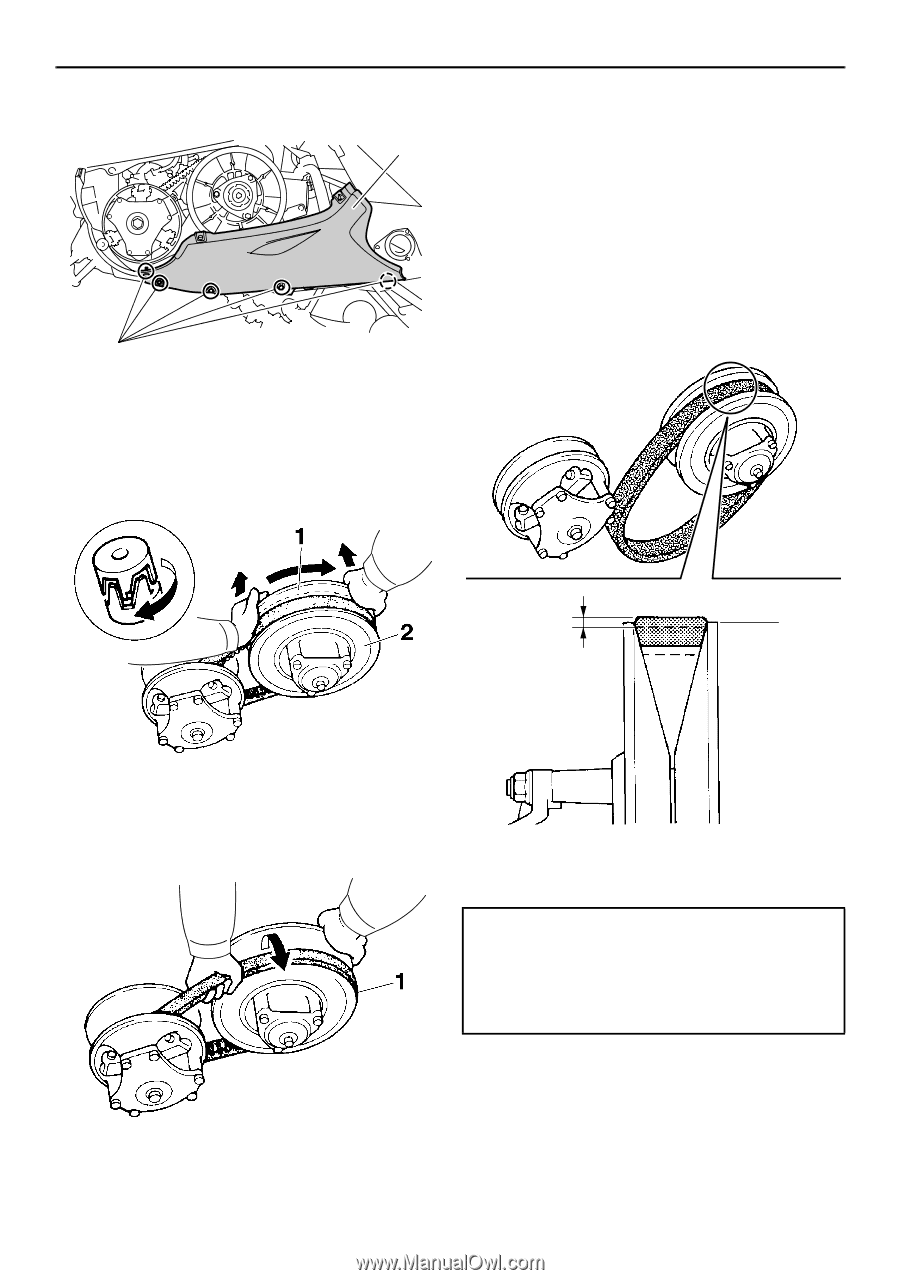
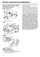
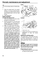
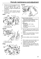
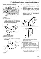
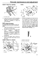
Periodic maintenance and adjustment RS90GT / RS90LTGT / RST90GT 6. 2 7. Remove the V-belt from the secondary sheave assembly and primary sheave assembly. Temporarily install the new V-belt on the secondary sheave assembly only, and then measure the V-belt position. Do not force the V-belt between the sheaves; the secondary sliding and fixed sheaves must touch each other. 1 1. Screw 2. Left lower cover 4. Rotate the secondary sliding sheave clockwise and push it so that it separates from the secondary fixed sheave. 2 1 1. Secondary sliding sheave 2. Secondary fixed sheave 5. Pull the V-belt up over the secondary fixed sheave. 1. Edge of the secondary sheave assembly 2. Standard V-belt position Standard V-belt position: From 1.5 mm (0.06 in) above the edge of the secondary sheave assembly to 0.5 mm (0.02 in) below the edge 8. If the V-belt position is incorrect, adjust it by removing or adding a spacer on each V-belt position adjusting bolt. 1. V-belt 89
-
 1
1 -
2
-
3
-
4
-
5
-
6
-
7
-
8
-
9
-
10
-
11
-
12
-
13
-
14
-
15
-
16
-
17
-
18
-
19
-
20
-
21
-
22
-
23
-
24
-
25
-
26
-
27
-
28
-
29
-
30
-
31
-
32
-
33
-
34
-
35
-
36
-
37
-
38
-
39
-
40
-
41
-
42
-
43
-
44
-
45
-
46
-
47
-
48
-
49
-
50
-
51
-
52
-
53
-
54
-
55
-
56
-
57
-
58
-
59
-
60
-
61
-
62
-
63
-
64
-
65
-
66
-
67
-
68
-
69
-
70
-
71
-
72
-
73
-
74
-
75
-
76
-
77
-
78
-
79
-
80
-
81
-
82
-
83
-
84
-
85
-
86
-
87
-
88
-
89
-
 90
90 -
 91
91 -
 92
92 -
 93
93 -
 94
94 -
 95
95 -
 96
96 -
 97
97 -
 98
98 -
 99
99 -
 100
100 -
101
-
102
-
103
-
104
-
105
-
106
-
107
-
108
-
109
-
110
-
111
-
112
-
113
-
114
-
115
-
116
-
117
-
118
-
119
-
120
-
121
-
122
-
123
-
124
-
125
-
126
-
127
-
128
-
129
-
130
-
131
-
132
-
133
-
134
-
135
-
136
-
137
-
138
-
139
-
140
 |
 |