2010 Yamaha Motorsports Royal Star Venture S Owners Manual - Page 35
2010 Yamaha Motorsports Royal Star Venture S Manual

Page 35 highlights
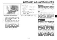
INSTRUMENT AND CONTROL FUNCTIONS EAU15303 Spring rate: Minimum (soft): Air pressure = 0 kPa (0 kgf/cm², 0 psi) Standard: Air pressure = 0 kPa (0 kgf/cm², 0 psi) Maximum (hard): Air pressure = 400 kPa (4.0 kgf/cm², 57 psi) 1. Shock absorber assembly air valve cap Sidestand The sidestand is located on the left side of the frame. Raise the sidestand or lower it with your foot while holding the vehicle upright. TIP The built-in sidestand switch is part of the ignition circuit cut-off system, which cuts the ignition in certain situations. (See page 4-20 for an explanation of the ignition circuit cut-off system.) EWA10240 5. Securely install the air valve cap. 4 3. Check the air pressure with the air pressure gauge included in the owner's tool kit. 4. To increase the spring rate and thereby harden the suspension, increase the air pressure with an air pump. To decrease the spring rate and thereby soften the suspension, decrease the air pressure by pushing the valve stem down. WARNING The vehicle must not be ridden with the sidestand down, or if the sidestand cannot be properly moved up (or does not stay up), otherwise the sidestand could contact the ground and distract the operator, resulting in a possible loss of control. Yamaha's ignition circuit cut-off system has been designed to assist the operator in fulfilling the responsibility of raising the sidestand before starting off. Therefore, check this system regularly as described 4-19
-
 1
1 -
2
-
3
-
4
-
5
-
6
-
7
-
8
-
9
-
10
-
11
-
12
-
13
-
14
-
15
-
16
-
17
-
18
-
19
-
20
-
21
-
22
-
23
-
24
-
25
-
26
-
27
-
28
-
29
-
 30
30 -
 31
31 -
 32
32 -
 33
33 -
 34
34 -
 35
35 -
 36
36 -
 37
37 -
 38
38 -
 39
39 -
 40
40 -
41
-
42
-
43
-
44
-
45
-
46
-
47
-
48
-
49
-
50
-
51
-
52
-
53
-
54
-
55
-
56
-
57
-
58
-
59
-
60
-
61
-
62
-
63
-
64
-
65
-
66
-
67
-
68
-
69
-
70
-
71
-
72
-
73
-
74
-
75
-
76
-
77
-
78
-
79
-
80
-
81
-
82
-
83
-
84
-
85
-
86
-
87
-
88
-
89
-
90
-
91
-
92
-
93
-
94
-
95
-
96
-
97
-
98
-
99
-
100
-
101
-
102
-
103
-
104
-
105
-
106
-
107
-
108
-
109
-
110
-
111
-
112
-
113
-
114
-
115
-
116
-
117
-
118
-
119
-
120
-
121
-
122
-
123
-
124
-
125
-
126
 |
 |
