2006 Yamaha Motorsports RS Vector Mountain Owners Manual - Page 69
2006 Yamaha Motorsports RS Vector Mountain Manual

Page 69 highlights
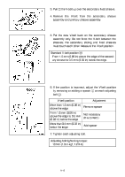
3. Pull 3 the V-belt up over the secondary fixed sheave. 4. Remove the V-belt from the secondary sheave assembly and primary sheave assembly. 5. Put the new V-belt back on the secondary sheave assembly only. Do not force the V-belt between the sheaves; the secondary sliding and fixed sheaves must touch each other. Measure the V-belt position. Standard V-belt position a: From 1.5 mm (0.06 in) above the edge of the secondary sheave to 0.5 mm (0.02 in) below the edge. 6. If the position is incorrect, adjust the V-belt position by removing or adding a spacer 4 on each adjusting bolt 5. CD-06E V-belt position More than 1.5 mm (0.06 in) above the edge From 1.5 mm (0.06 in) above the edge to 0.5 mm (0.02 in) below the edge More than 0.5 mm (0.02 in) below the edge Adjustment Remove spacer Not necessary (It is correct.) Add spacer 7. Tighten each adjusting bolt. Adjusting bolt tightening torque: 10 Nm (1.0 m·kgf, 7.2 ft·lb) 8-15
-
 1
1 -
2
-
3
-
4
-
5
-
6
-
7
-
8
-
9
-
10
-
11
-
12
-
13
-
14
-
15
-
16
-
17
-
18
-
19
-
20
-
21
-
22
-
23
-
24
-
25
-
26
-
27
-
28
-
29
-
30
-
31
-
32
-
33
-
34
-
35
-
36
-
37
-
38
-
39
-
40
-
41
-
42
-
43
-
44
-
45
-
46
-
47
-
48
-
49
-
50
-
51
-
52
-
53
-
54
-
55
-
56
-
57
-
58
-
59
-
60
-
61
-
62
-
63
-
 64
64 -
 65
65 -
 66
66 -
 67
67 -
 68
68 -
 69
69 -
 70
70 -
 71
71 -
 72
72 -
 73
73 -
 74
74 -
75
-
76
-
77
-
78
-
79
-
80
-
81
-
82
-
83
-
84
-
85
-
86
-
87
-
88
-
89
-
90
-
91
-
92
-
93
-
94
-
95
-
96
-
97
-
98
-
99
-
100
-
101
-
102
-
103
-
104
 |
 |
