2005 Yamaha Motorsports RS Venture Owners Manual - Page 77
2005 Yamaha Motorsports RS Venture Manual

Page 77 highlights
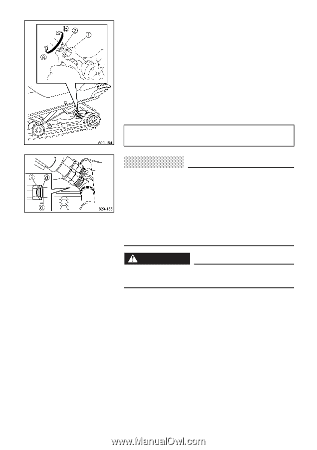
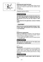
ESU04220 Control rod adjustment The weight transfer can be adjusted by turning the control rod adjusting nut 1. 1. Loosen the locknut 2 while holding the control rod adjusting nut. 2. Turn the adjusting nut in direction a to increase weight transfer or direction b to decrease weight transfer. 3. Tighten the locknut while holding the adjusting nut in place. Locknut tightening torque: 25 Nm (2.5 m·kgf, 18 ft·lb) CAUTION: @ G G When using the two wrenches included in the owner's tool kit, make sure that they are situated at a right angle to the control rod as shown, and that they are tightly fitted to the locknut and the control rod adjusting nut. The left and right adjusting nuts must be set to the same position. Uneven settings can cause poor handling and loss of stability. @ WARNING @ Never adjust the control rods beyond the maximum range indicated on the rods with red paint 3. @ c Adjustable range d Standard position 8-23
-
 1
1 -
2
-
3
-
4
-
5
-
6
-
7
-
8
-
9
-
10
-
11
-
12
-
13
-
14
-
15
-
16
-
17
-
18
-
19
-
20
-
21
-
22
-
23
-
24
-
25
-
26
-
27
-
28
-
29
-
30
-
31
-
32
-
33
-
34
-
35
-
36
-
37
-
38
-
39
-
40
-
41
-
42
-
43
-
44
-
45
-
46
-
47
-
48
-
49
-
50
-
51
-
52
-
53
-
54
-
55
-
56
-
57
-
58
-
59
-
60
-
61
-
62
-
63
-
64
-
65
-
66
-
67
-
68
-
69
-
70
-
71
-
 72
72 -
 73
73 -
 74
74 -
 75
75 -
 76
76 -
 77
77 -
 78
78 -
 79
79 -
 80
80 -
 81
81 -
 82
82 -
83
-
84
-
85
-
86
-
87
-
88
-
89
-
90
-
91
-
92
-
93
-
94
-
95
-
96
-
97
-
98
-
99
 |
 |