Viper VSS4000 Addendum
Viper VSS4000 Manual
 |
View all Viper VSS4000 manuals
Add to My Manuals
Save this manual to your list of manuals |
Viper VSS4000 manual content summary:
- Viper VSS4000 | Addendum - Page 1
Addendum: Installation Guide ! ATTENTION INSTALLER ! The VSS4000 integrates the Viper 5101 Remote Start with the VSM100 Viper SmartStart Module. Read this addendum and both installation guides thoroughly before beginning. They will help you understand how to combine the two systems, avoid mistakes, - Viper VSS4000 | Addendum - Page 2
9 What's included: Correction The VSS4000 system includes: This list has changed to integrate two systems, see Correction column. VSM100 Viper SmartStart module, wire harness, Quick reference User's & Installation guide. Module ID stickers. 5101V remote start/keyless entry main module, Owner
-
 1
1 -
 2
2
 |
 |
ADVSS4000 2009-09
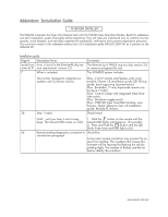
Addendum: Installation Guide
! ATTENTION INSTALLER !
The VSS4000 integrates the Viper 5101 Remote Start with the VSM100 Viper SmartStart Module. Read this addendum
and both installation guides thoroughly before beginning. They will help you understand how to combine the two
systems, avoid mistakes, and smoothly complete the installation, verification and customer registration processes.
The corrections made in this addendum address the 5101 installation guide (N4102V 2008-06) as it pertains to the
VSN4000 kit.
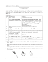
Installation guide
Page #
Description/error
Correction
Inside front
cover & 31
Error is found in the Bitwriter® chip ver-
sion requirement: version
2.5
The Bitwriter (p/n 998U) requires chip version
2.6
or newer to program this unit.
7
What is included:
This list has changed to integrate two
systems, see Correction column.
The VSS4000 system includes:
One - 5101V remote start/keyless entry main
module, Owner's & Installation guide, QR Wiring
guide, (and supporting documentation).
One - five-button /1-way Supercode remote con-
trol (p/n 7153V)
One - Control Center with integrated Valet Over-
ride switch
One - Shutdown toggle switch
One - VSM100 Viper SmartStart module, wire
harness, Quick reference User's & Installation
guide. Module ID stickers.
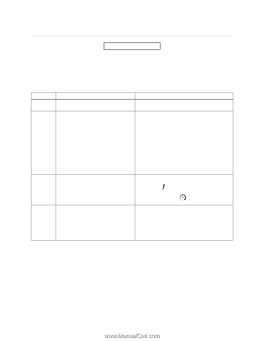
36
Step 1 reads:
Hold
....
until you hear it emit a long
beep. The transmit LED comes on solid.
Should read:
1.
Hold the
button on the remote until the
transmit LED lights solid (approx. 10 seconds).
2.
Press and hold the
button until the LED
blinks three times and then lights solid.
56
Remote starting diagnostics correction to
introduction paragraph
Should be:
A few select system conditions may prevent the en-
gine from starting. The condition that causes this
non-start will be reported by flashing the vehicle
parking lights. The number of flashes and the list
below identify the condition.