URC MRF-350 Owners Manual
URC MRF-350 Manual
 |
View all URC MRF-350 manuals
Add to My Manuals
Save this manual to your list of manuals |
URC MRF-350 manual content summary:
- URC MRF-350 | Owners Manual - Page 1
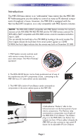
MRF-350 Installation Manual Optimizing Narrow Band Reception with the RFX-250 and MSC System Remotes - URC MRF-350 | Owners Manual - Page 2
MRF-350 Installation Manual ©2006 - 2013 Universal Remote Control, Inc. The information in this owner's manual is copyright protected. No part of this manual may be copied or reproduced in any form without prior written consent from Universal Remote Control, Inc. UNIVERSAL REMOTE CONTROL, INC. SHALL - URC MRF-350 | Owners Manual - Page 3
TABLE OF CONTENTS Introduction 1 Features and Benefits 2 Parts Guide 2 Optimizing Range and Reliability 3 Connecting IR and Setting Output Levels 6 Front Blaster Overload 7 Disabling the Front Blaster - Step by Step via PC 7 Controlling An Array of Identical Components or Zones 8 - URC MRF-350 | Owners Manual - Page 4
is only compatible with MSC System remotes. 1. MSC System remote controls send radio waves in every direction, so your client enjoys "No More Pointing" operation! 2. The RFX-250 RF Sensor can be freely positioned out of way of the interference the A/V components create, connecting to the MRF-350 via - URC MRF-350 | Owners Manual - Page 5
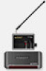
(does not support IR routing). The 5V, 100 milliamp output will directly power some brands and models of keypad directly. Parts Guide The MRF-350 RF Base Station includes: 1 - RFX-250 RF Sensor with integrated antenna 1 - Mounting plate for RFX-250 1 - MRF-350 Base Station 1 - Mounting Plate - URC MRF-350 | Owners Manual - Page 6
MRF-350 itself. 4. Connect the RFX-250 to the MRF-350's RF INPUT. You can connect to either the screw connector or the jack as shown: When connecting a single RFX-250 to the MRF-350 utilize the cable with 3.5 mm plugs on both ends. When you need a longer wire or are connecting up to three RFX-250s - URC MRF-350 | Owners Manual - Page 7
are pressed on any remote control, no valid RF transmissions are being received. The flickering or glowing RF LED warns you that the RFX-250 is detecting RF interference generated or reflected near this location. MOVE the RFX-250 to a new location. 6. Observe the STATUS LED of the MRF-350. It is - URC MRF-350 | Owners Manual - Page 8
remote and the MRF-350 to the same VALID RF ID#. Keep in mind that zero (0) is not a valid RF ID#. Watch the STATUS LED on MRF-350 - it should light every time you press a button on the remote. This will tell you that the signal was received and understood. You can ignore the RF LED on the RFX-250 - URC MRF-350 | Owners Manual - Page 9
(Tip of the Plug). When connecting to a components rear panel IR Input, cut the flasher off of the wire, strip the two conductors and connect to the rear panel IR Input. The MRF-350 is only compatible with standard IR Inputs, not proprietary control systems offered by some manufacturers. Page 6 - URC MRF-350 | Owners Manual - Page 10
MX PC programmable remote control into the PC. Open your saved configuration and follow these steps to turn off the front blaster: Step 1 - Open the RF Setup Window The RF Setup window opens after selecting RF Control from the Program Menu. Step 2 - Setup the Receiver Extend the RF Setup window by - URC MRF-350 | Owners Manual - Page 11
MRF-350 BASE STATION Controlling An Array of Identical Components or Zones There are several considerations to take into account when you are installing an MRF-350 to control an array of identical components: 1. The RF ID# cannot be set to Code 0, the universal setting. You must use one of the - URC MRF-350 | Owners Manual - Page 12
MRF-350 BASE STATION Step 3 Save your work. Step 5 - Open the RF Setup Window The RF Setup window opens after selecting RF Control from the Program Menu. The RF Setup window is send both IR and RF commands. If you look at the column for Flashers, you can see that the default sends IR commands for - URC MRF-350 | Owners Manual - Page 13
MRF-350 BASE STATION Click on the "cell" for the first identical TV, by crossing the device row with the Signals column. Signal Column TV1 Device Row Select RF from the three options shown for EACH of the identical TVs. You may leave the other components of the system set to IR & RF. Step 7 - - URC MRF-350 | Owners Manual - Page 14
MRF-350 BASE STATION Programming For Multiple Equipment Locations You can operate up to 15 different equipment locations, each with an MRF350 assigned a unique Receiver ID#. You program each of your remotes to talk to the equipment locations you want by assigning each of your devices to a receiver. - URC MRF-350 | Owners Manual - Page 15
RF ID# is set to 0, IR routing does NOT work. The RF ID# from 1-9 or A-F must be set on both the remote control and the bottom of the MRF-350, second, check that the flasher level is set to the minimum necessary, third, check that the emitter is facing the component, fourth, make sure the RFX-250 - URC MRF-350 | Owners Manual - Page 16
MRF-350 BASE STATION Limited Warranty Statement 1. Limited Warranty and Disclaimers Universal Remote Control, Inc. ("URC") warrants that the URC equipment shall be free from defects in material and workmanship under normal usage for one (1) year from purchase when such is purchased from URC SERVICES - URC MRF-350 | Owners Manual - Page 17
. With the exception of URC's IR-only, broad-based consumer remotes, none of URC's PC programmable remotes or any of our Total Control® whole-house equipment are authorized for online internet sales. Buying URC's PC programmable remotes or any of our Total Control® whole-house equipment online - URC MRF-350 | Owners Manual - Page 18
MRF-350 BASE STATION 2. URC'S Limitations of Liability IN NO EVENT SHALL URC BE LIABLE FOR INDIRECT, SPECIAL, INCIDENTAL, EXEMPLARY, PUNITIVE OR CONSEQUENTIAL DAMAGES OF ANY KIND OR LOSS OF PROFITS OR BUSINESS OPPORTUNITY, EVEN IF URC IS ADVISED OF THE POSSIBILITY OF SUCH DAMAGES. IN NO EVENT SHALL - URC MRF-350 | Owners Manual - Page 19
- URC MRF-350 | Owners Manual - Page 20
with the instructions, may cause harmful interference to radio communications. However, there is no guarantee that interference will not the interference by one more of the following measures: u Reorient or relocate the receiving antenna. u Increase the separation between the equipment and receiv-
-
 1
1 -
 2
2 -
 3
3 -
 4
4 -
 5
5 -
 6
6 -
 7
7 -
8
-
9
-
10
-
11
-
12
-
13
-
14
-
15
-
16
-
17
-
18
-
19
-
20
 |
 |
MRF-350 Installation Manual
Optimizing Narrow Band Reception with
the RFX-250 and MSC System Remotes