URC MRF-300 Owners Manual
URC MRF-300 Manual
 |
View all URC MRF-300 manuals
Add to My Manuals
Save this manual to your list of manuals |
URC MRF-300 manual content summary:
- URC MRF-300 | Owners Manual - Page 1
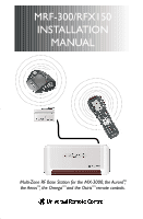
MRF-300/RFX150 INSTALLATION MANUAL Multi-Zone RF Base Station for the MX-3000, the AuroraTM, the AerosTM, the OmegaTM and the OsirisTM remote controls. - URC MRF-300 | Owners Manual - Page 2
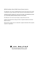
MRF-300 Installation Manual ©2005 Universal Remote Control, Inc. The information in this manual is copyright protected. No part of this manual may be copied or reproduced in any form without prior written consent from Universal Remote Control, Inc. UNIVERSAL REMOTE CONTROL, INC. SHALL NOT BE LIABLE - URC MRF-300 | Owners Manual - Page 3
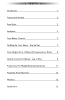
TABLE OF CONTENTS Introduction 1 Features and Benefits 2 Parts Guide 2 Installation 3 Front Blaster Overload 7 Disabling the Front Blaster - Step by Step 7 Controlling An Array of Identical Components or Zones 8 Identical Components/Zones - Step by Step 8 - URC MRF-300 | Owners Manual - Page 4
MRF-300 BASE STATION Introduction The MRF-300 base station is an "addressable" base station. It is only compatible with Universal Remote Control's line of Custom Programmed Remotes with RF Addressing such as the MX-3000, the MX-950 Aurora, the MX-850 Aeros, the MX-800, MX-650 Omega and the MX-350 - URC MRF-300 | Owners Manual - Page 5
all IR line outputs (does not support IR routing).The 5V, 100 milliamp output will directly power some brands and models of keypad directly. Parts Guide The MRF-300 RF Base Station includes: 1 - RFX-150 RF Sensor with integrated antenna 1 - MRF-300 Base Station 1 - Mounting Plate for wall mounting - URC MRF-300 | Owners Manual - Page 6
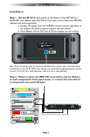
MRF-300 BASE STATION Installation Step 1 - Set the RF ID # rotary switch on the bottom of the MRF-300 to a VALID ID# (any address other than ID# 0). If you leave it set to ID# 0, the MRF-300 operates with some restrictions: a. Accepts RF signals from any 418MHZ remote control regardless of the - URC MRF-300 | Owners Manual - Page 7
the first MRF-300 to the RF IN of the next MRF-300. Step 3 - Connect the RFX-150 to the RF IN, but DO NOT MOUNT IT! Plug the 3.5mm plug into the RFX-150's RF OUT jack. Connect the other end of the cable to one of the two RF IN on the MRF-300, When connecting a single RFX-150 to the MRF300 utilize - URC MRF-300 | Owners Manual - Page 8
MRF-300 BASE STATION Step 4 - Connect the Power Supply to the MRF-300. The POWER LED's on both the RFX-150 and the MRF-300 should light up when the Power Supply is connected. Step 5 - Power on the entire Audio/Video System Test for RF Interference The RF LED lights when any RF signal is detected. - URC MRF-300 | Owners Manual - Page 9
MRF-300 BASE STATION Step 7 - Test RF Address Test that pressing a button on the remote control lights the STATUS LED of the MRF-300.The STATUS LED only lights when the correct RF address is received. Step 8 - Adjust IR Line Output Levels Adjust each of the IR Line Output levels for best operation. - URC MRF-300 | Owners Manual - Page 10
six components you can purchase an additional MRF-300. Disabling the Front Blaster - Step by Step via PC Note: If you are programming a URC MX "addressable" remote control that sets up without a PC, refer to the owners manual to disable the Front Blaster. Open the PC software, then plug the MX PC - URC MRF-300 | Owners Manual - Page 11
MRF-300 BASE STATION Controlling An Array of Identical Components or Zones There are several considerations to take into account when you are installing an MRF-300 to control an array of identical components: 1.The RF ID# cannot be set to Code 0, the universal setting.You must use one of the fifteen - URC MRF-300 | Owners Manual - Page 12
MRF-300 BASE STATION Step 3 - Copy The Programmed Device In tree view, right click on the device you , you can see that the factory default programming sets all of the devices to send both IR and RF commands. If you look at the column for Flashers, you can see that the default sends IR commands - URC MRF-300 | Owners Manual - Page 13
MRF-300 BASE STATION Click on the "cell" for the first identical TV, by crossing the device row with the Signals column. Signal Column TV1 Device Row Select RF from the three options shown for EACH of the identical TV's.You may leave the other components of the system set to IR & RF. Step 7 - - URC MRF-300 | Owners Manual - Page 14
MRF-300 BASE STATION Programming For Multiple Equipment Locations You can operate up to 15 different equipment locations, each with an MRF300 assigned a unique Receiver ID# Using the controls at the bottom extended portion of the RF Control window, add new receivers and rename them for the Add new - URC MRF-300 | Owners Manual - Page 15
additional RFX-150 RF Sensors in the areas with poor range by concealing wire runs to nearby attic or crawl space locations. Warranty The MRF-300 is covered against any manufacturers defects or workmanship for a period of one year from the date of purchase if purchased from an authorized Universal - URC MRF-300 | Owners Manual - Page 16
The Complete ControlTM Remote Control System 500 Mamaroneck Avenue, Harrison, NY 10528 Phone: (914) 835-4484 Fax: (914) 835-4532 www.universalremote.com
-
 1
1 -
 2
2 -
 3
3 -
 4
4 -
 5
5 -
 6
6 -
 7
7 -
8
-
9
-
10
-
11
-
12
-
13
-
14
-
15
-
16
 |
 |
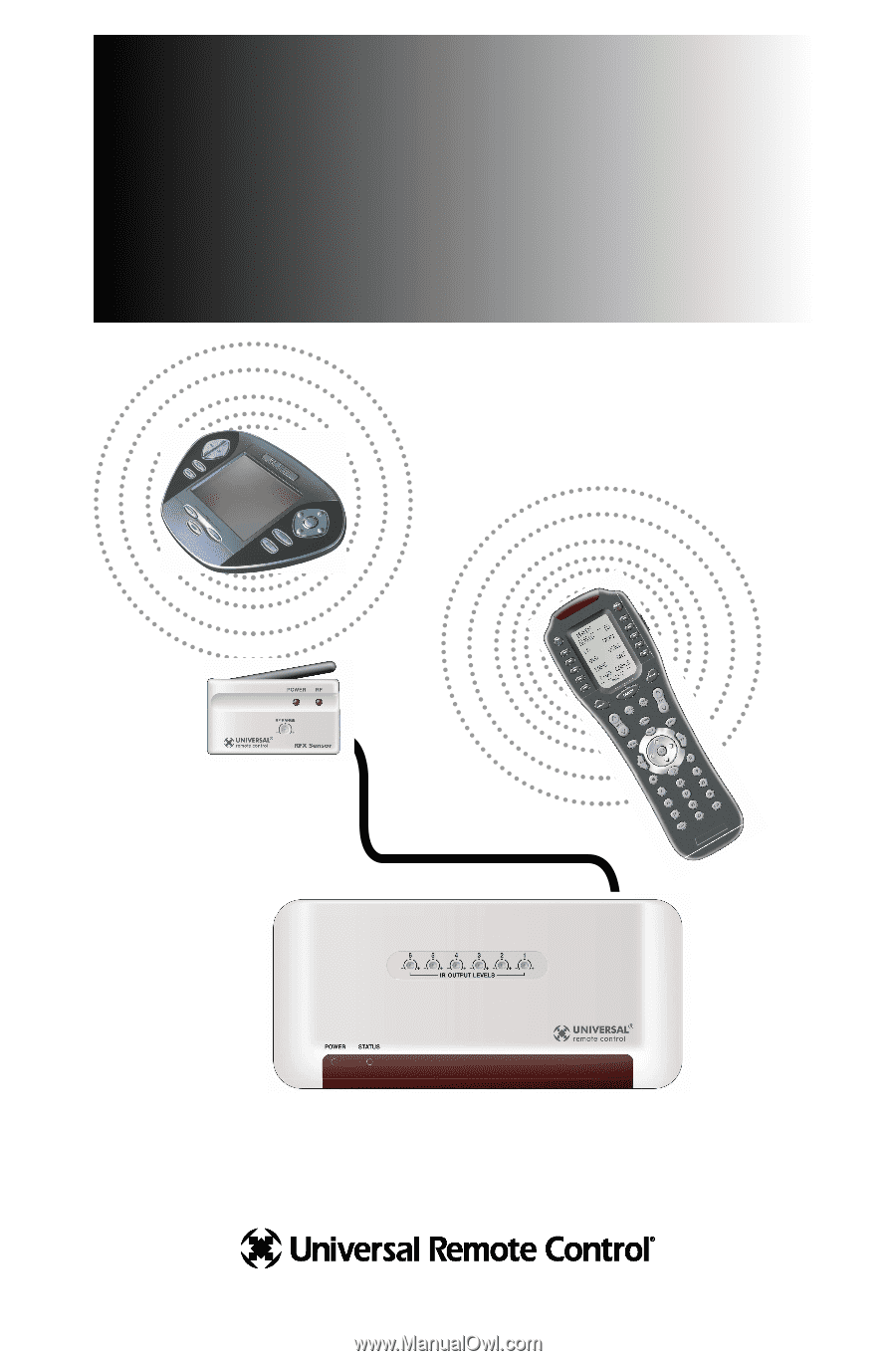
MRF-300/RFX150
INSTALLATION
MANUAL
Multi-Zone RF Base Station for the MX-3000, the Aurora ,
the Aeros
, the Omega
and the Osiris
remote controls.
TM
TM
TM
TM