Sub-Zero IC-24FI Integrated Installation Guide
Sub-Zero IC-24FI Manual
 |
View all Sub-Zero IC-24FI manuals
Add to My Manuals
Save this manual to your list of manuals |
Sub-Zero IC-24FI manual content summary:
- Sub-Zero IC-24FI | Integrated Installation Guide - Page 1
Integrated Refrigeration Installation Guide - Sub-Zero IC-24FI | Integrated Installation Guide - Page 2
take note of the following types of highlighted information throughout this guide: IMPORTANT NOTE highlights information that is especially important. CAUTION indicates a situation where minor injury or product damage may occur if instructions are not followed. WARNING states a hazard that may cause - Sub-Zero IC-24FI | Integrated Installation Guide - Page 3
. For column models, the rating plate is located inside the middle drawer near the drawer guide opposite the hinge. For tall and drawer models, the rating plate is located inside the cabinet, to the left of the upper drawer. Refer to the illustrations below. If service is necessary, contact Sub-Zero - Sub-Zero IC-24FI | Integrated Installation Guide - Page 4
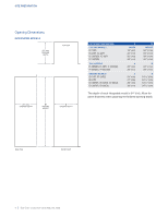
635) OPENING DEPTH B OPENING HEIGHT A OPENING WIDTH OPENING DIMENSIONS COLUMN MODELS IC-18FI IC-24R, IC-24FI IC-30R(ID), IC-30FI IC-36R(ID) TALL MODELS IT-30R(ID), IT-30FI, IT-30CI(ID) IT-36R(ID), IT-36CI(ID) DRAWER MODELS ID-24R, ID-24F(I) ID-27R ID-30R(P), ID-30F(I), ID-30C(I) ID-36R(P), ID-36C - Sub-Zero IC-24FI | Integrated Installation Guide - Page 5
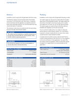
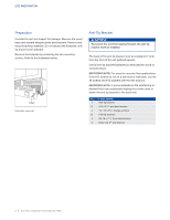
shown in the illustration and chart below. A separate circuit, servicing only this appliance is required. A ground fault circuit interrupter ( not interfere with installation of the anti-tip bracket. Column and tall models with an ice maker or water dispenser feature a water filtration system. An - Sub-Zero IC-24FI | Integrated Installation Guide - Page 6
610) from the front of the unit (without panels). Use all anti-tip bracket hardware as instructed for wood or concrete floors. IMPORTANT NOTE: For wood or concrete floor applications, if the # 4 #8-18 x 11/4" truss head screws 4 Nylon Zip-it® wall anchors 6 | Sub-Zero Customer Care 800.222.7820 - Sub-Zero IC-24FI | Integrated Installation Guide - Page 7
or wall plate a minimum of 3/4" (19). Refer to the illustration and chart below. ANTI-TIP BRACKET PLACEMENT WIDTH 18" Models 24" Models 27" Models 30" Models 36" Models A 9" (229) 12" (305) 131/2" (343) 15" (318) 18" (457) CONCRETE WEDGE ANCHOR INSTALLATION: 1 Drill a 3/8" (10) diameter hole any - Sub-Zero IC-24FI | Integrated Installation Guide - Page 8
the unit tipping forward, the front leveling legs must be in contact with the floor. FRONT LEG ADJUSTMENT REAR LEG ADJUSTMENT Front adjustment. Rear adjustment. 8 | Sub-Zero Customer Care 800.222.7820 - Sub-Zero IC-24FI | Integrated Installation Guide - Page 9
INSTALLATION Alignment DEPTH ADJUSTMENT Adjust the depth of the unit to fit flush with surrounding cabinetry. Follow these steps for a precision fit: 1 Place decorative panel on a protected work surface. Place the panel thickness gauge next to the panel to determine which notch corresponds with the - Sub-Zero IC-24FI | Integrated Installation Guide - Page 10
models, custom door panels and handle hardware must be installed. Stainless steel panels are available through an authorized Sub-Zero finished opening depth. PANEL REQUIREMENTS COLUMN 18" Models 24" Models 30" / 36" Models TALL (DOOR) 30" Models 36" Models DRAWER All Drawer Panels PANEL THICKNESS - Sub-Zero IC-24FI | Integrated Installation Guide - Page 11
FLOOR VENTED LOUVERS 24" (610) TO BACK OF UNIT 11/8" (29) MAX TOE KICK ADJUSTMENT A DECORATIVE TOE KICK CANNOT EXTEND BEYOND THIS PLANE Upper valance (column and tall models)-side view. Toe kick area-side view. subzero.com | 11 - Sub-Zero IC-24FI | Integrated Installation Guide - Page 12
both door mounting brackets. Opening the door slightly may help with alignment. Once the panel is supported by the screws, partially insert a #8 x 1/2" screw into the second hole from the Door panel template-bottom (tall models only). Door panel mounting. 12 | Sub-Zero Customer Care 800.222.7820 - Sub-Zero IC-24FI | Integrated Installation Guide - Page 13
the slotted holes on both drawer mounting brackets. Refer to the illustration below. Opening the drawer slightly may help with alignment. Once the panel is supported by the screws, partially insert a #8 x 1/2" screw into the second hole from the bottom on each side of the panel, but do not tighten - Sub-Zero IC-24FI | Integrated Installation Guide - Page 14
illustration below. SIDE TRIM INSTALLATION Install the decorative trim strip to the handle side of tall and column models. The side trim snaps over the bracket attached to the handle side of the unit. Refer trim. Side trim. Inner top trim. Outer top trim. 14 | Sub-Zero Customer Care 800.222.7820 - Sub-Zero IC-24FI | Integrated Installation Guide - Page 15
the hinges of tall and column units. To limit the door Sub-Zero, Sub-Zero & Design, Dual Refrigeration, Constant Care, The Living Kitchen, Great American Kitchens The Fine Art of Kitchen Design, and Ingredients are registered trademarks and service marks of Sub-Zero, Inc. Wolf, Wolf & Design, Wolf - Sub-Zero IC-24FI | Integrated Installation Guide - Page 16
precauciones. AVISO IMPORTANTE: En toda esta guía, las dimensiones entre paréntesis son milímetros, a menos que se especifique lo contrario. 2 | Atención al cliente de Sub-Zero 800.222.7820 - Sub-Zero IC-24FI | Integrated Installation Guide - Page 17
la izquierda del cajón superior del refrigerador. Consulte las siguientes ilustraciones. Si necesita servicio, póngase en contacto con el centro de servicio autorizado de Sub-Zero y tenga a la mano el modelo y número de serie de la unidad. Para obtener los datos del centro de servicio autorizado de - Sub-Zero IC-24FI | Integrated Installation Guide - Page 18
LA ABERTURA A ANCHURA DE ABERTURA DIMENSIONES DE ABERTURA MODELOS DE COLUMNA IC-18FI IC-24R, IC-24FI IC-30R(ID), IC-30FI IC-36R(ID) MODELOS ALTOS IT-30R(ID), IT-30FI, IT-30CI(ID) IT-36R(ID), IT-36CI(ID) MODELOS CON . VISTA LATERAL VISTA FRONTAL 4 | Atención al cliente de Sub-Zero 800.222.7820 - Sub-Zero IC-24FI | Integrated Installation Guide - Page 19
PREPARACIÓN DEL SITIO Instalación eléctrica La instalación debe cumplir con todos los códigos eléctricos vigentes. El suministro eléctrico debe colocarse dentro del área sombreada que se muestra en la siguiente ilustración. Es necesario un circuito independiente, que dé servicio únicamente a este - Sub-Zero IC-24FI | Integrated Installation Guide - Page 20
de cuña de 3/8"-16 x 33/4" 12 Arandelas planas #12 4 Tornillos de cabeza segmentada #8-18 x 11/4" 4 Anclajes Nylon Zip-it® para pared 6 | Atención al cliente de Sub-Zero 800.222.7820 - Sub-Zero IC-24FI | Integrated Installation Guide - Page 21
PREPARACIÓN DEL SITIO Soporte antivuelco APLICACIÓN EN SUELO DE MADERA Después de ubicar apropiadamente el soporte antivuelco en la abertura, taladre los orificios guía con un diámetro máximo de 3/16" (5) en los travesaños o en la placa de la pared. Utilice los tornillos #12 y las arandelas para - Sub-Zero IC-24FI | Integrated Installation Guide - Page 22
deben estar en contacto con el suelo. AJUSTE DE LA PATA DELANTERA AJUSTE DE LA PATA TRASERA Ajuste frontal. Ajuste posterior. 8 | Atención al cliente de Sub-Zero 800.222.7820 - Sub-Zero IC-24FI | Integrated Installation Guide - Page 23
INSTALACIÓN Alineación AJUSTE DE LA PROFUNDIDAD Ajuste la profundidad de la unidad para que quede a ras con los gabinetes que la rodean. Para un ajuste de precisión siga estos pasos: 1 Coloque el panel decorativo sobre una superficie de trabajo protegida. Coloque el calibrador del grosor del panel - Sub-Zero IC-24FI | Integrated Installation Guide - Page 24
instalación se requiere un kit de instalación doble. Los kits de instalación doble están disponibles a través de un distribuidor autorizado de Sub-Zero. Para obtener más información acerca de los distribuidores locales, visite la sección para encontrar una sala de exhibición de nuestro sitio web - Sub-Zero IC-24FI | Integrated Installation Guide - Page 25
INSTALACIÓN DE LOS PANELES Paneles personalizados ALTURA DEL PANEL DE LA PUERTA La altura del panel personalizado de la puerta puede ser mayor a su altura típica, siempre y cuando no se exceda el límite de peso. Consulte la siguiente ilustración. ESPACIO DEL ZÓCALO La altura de la zona del zócalo - Sub-Zero IC-24FI | Integrated Installation Guide - Page 26
puerta - Plantilla del panel de la puerta - parte superior parte inferior (modelos altos únicamente). Montaje del panel de la puerta. 12 | Atención al cliente de Sub-Zero 800.222.7820 - Sub-Zero IC-24FI | Integrated Installation Guide - Page 27
INSTALACIÓN DE LOS PANELES Instalación de los paneles INSTALACIÓN DEL PANEL DEL CAJÓN Coloque el panel boca abajo sobre una superficie de trabajo protegida. Coloque la plantilla a ras con la parte superior y los lados del panel. Compruebe que está usando el lado correcto de la plantilla, luego - Sub-Zero IC-24FI | Integrated Installation Guide - Page 28
. Consulte la siguiente ilustración. RIBETE DE LA PUERTA Ribete de la puerta. Ribete lateral. Ribete superior interno. Ribete superior externo. 14 | Atención al cliente de Sub-Zero 800.222.7820 - Sub-Zero IC-24FI | Integrated Installation Guide - Page 29
para puerta a 90°. Sub-Zero, Sub-Zero & Design, Dual Refrigeration, Constant Care, The Living Kitchen, Great American Kitchens The Fine Art of Kitchen Design e Ingredients son marcas comerciales registradas y marcas de servicio de Sub-Zero, Inc. Wolf, Wolf & Design, Wolf Gourmet, W & Design y el - Sub-Zero IC-24FI | Integrated Installation Guide - Page 30
4 Dimensions de l'ouverture 5 Électricité 5 Plomberie 6 Préparation 6 Support antibasculement 8 Mise en place 8 Alignement 9 Tuyau d'alimentation en eau 10 ce guide, les dimensions entre parenthèses sont en millimètres à moins d'indication contraire. 2 | Atención al cliente de Sub-Zero 800.222.7820 - Sub-Zero IC-24FI | Integrated Installation Guide - Page 31
guide du tiroir à l'opposé de la charnière. Pour les modèles en hauteur et à tiroirs, la plaque signalétique se trouve à l'intérieur de l'armoire à la gauche du tiroir supérieur. Reportez-vous aux illustrations ci-dessous. Si vous avez besoin de service, communiquez avec le service Sub-Zero certifi - Sub-Zero IC-24FI | Integrated Installation Guide - Page 32
L'OUVERTURE A LARGEUR DE L'OUVERTURE DIMENSIONS DE L'OUVERTURE MODÈLES EN COLONNE IC-18FI IC-24R, IC-24FI IC-30R(ID), IC-30FI IC-36R(ID) MODÈLES EN HAUTEUR IT-30R(ID), IT-30FI, IT-30CI(ID) IT-36R(ID), IT-36CI(ID) MODÈLES VUE DE PROFIL VUE DE FACE 4 | Atención al cliente de Sub-Zero 800.222.7820 - Sub-Zero IC-24FI | Integrated Installation Guide - Page 33
. N'utilisez pas des vannes à auto-perçage. Le tuyau d'alimentation en eau doit être au ras du sol et ne pas nuire à l'installation du support antibasculement. Les modèles en colonne et en hauteur avec une machine à glaçons ou un distributeur d'eau comprennent un système de filtration d'eau. - Sub-Zero IC-24FI | Integrated Installation Guide - Page 34
support Support antibasculement 12 Vis à tête cylindrique bombée n°12 x 21/2 po 4 Cales d'ancrage de 3/8 po-16 x 33/4 po 12 Rondelles plates n°12 4 Vis à tête bombée n°8-18 x 11/4 po 4 Dispositifs d'ancrage au mur à glissière en nylon Zip-it® 6 | Atención al cliente de Sub-Zero - Sub-Zero IC-24FI | Integrated Installation Guide - Page 35
la plaque murale. Utilisez les vis et les rondelles n° 12 pour fixer les supports. Vérifiez que les vis pénètrent dans le matériau du plancher et dans Reportez-vous à l'illustration et au tableau ci-dessous. MISE EN PLACE DU SUPPORT ANTIBASCULEMENT LARGEUR Modèles de 18 po Modèles de 24 po Modèles - Sub-Zero IC-24FI | Integrated Installation Guide - Page 36
alimentation dans une prise mise à la terre et roulez l'unité en place. Vérifiez que le support antibasculement est correctement enclenché. Alignement NIVELLEMENT Une fois l'unité en place, le réglage de la ARRIÈRE Réglage avant. Réglage arrière. 8 | Atención al cliente de Sub-Zero 800.222.7820 - Sub-Zero IC-24FI | Integrated Installation Guide - Page 37
INSTALLATION Alignement RÉGLAGE DE LA PROFONDEUR Réglez la profondeur de l'unité afin qu'elle soit à égalité avec les armoires adjacentes. Suivez les étapes suivantes pour effectuer un réglage précis : 1 Placez le panneau décoratif sur une surface de travail protégée. Placez la jauge d'épaisseur de - Sub-Zero IC-24FI | Integrated Installation Guide - Page 38
offertes par les dépositaires Sub-Zero autorisés. Pour obtenir des renseignements sur le dépositaire local, visitez la section Trouver une salle d'exposition de notre site Web, subzero. com. Pour des questions concernant l'installation, appelez le service à la clientèle de Sub-Zero au 800-222-7820 - Sub-Zero IC-24FI | Integrated Installation Guide - Page 39
INSTALLATION DES PANNEAUX Panneaux personnalisés HAUTEUR DU PANNEAU DE PORTE La hauteur du panneau de porte personnalisé peut se prolonger au-delà de la hauteur typique d'un panneau à condition de ne pas dépasser la limite de poids. Reportezvous à l'illustration ci-dessous. DÉGAGEMENT DE LA PLAQUE - Sub-Zero IC-24FI | Integrated Installation Guide - Page 40
Alignez les vis de soutien à l'arrière du panneau avec les trous allongés sur les deux supports de montage de porte. Ouvrir la porte légèrement peut aider à effectuer l'alignement. Une fois le panneau seulement). Montage du panneau de porte. 12 | Atención al cliente de Sub-Zero 800.222.7820 - Sub-Zero IC-24FI | Integrated Installation Guide - Page 41
le poids du panneau pendant l'installation. Alignez les vis de soutien à l'arrière du panneau avec les trous allongés sur les deux supports de montage de tiroir. Reportez-vous à l'illustration ci-dessous. Ouvrir le tiroir légèrement peut aider à effectuer l'alignement. Une fois le panneau soutenu - Sub-Zero IC-24FI | Integrated Installation Guide - Page 42
la garniture décorative latérale sur la porte/les tiroirs. Pour installer, alignez la garniture avec le support sur le côté de la porte/du tiroir et enclenchez en place, en poussant la garniture vers l'arri érieure. Garniture supérieure extérieure. 14 | Atención al cliente de Sub-Zero 800.222.7820 - Sub-Zero IC-24FI | Integrated Installation Guide - Page 43
Butée de porte de 90°. Sub-Zero, Sub-Zero & Design, Dual Refrigeration, Constant Care, The Living Kitchen, Great American Kitchens The Fine Art of Kitchen Design, et Ingredients sont des marques déposées et des marques de service de Sub-Zero, Inc. Wolf, Wolf & Design, Wolf Gourmet, W & Design et la - Sub-Zero IC-24FI | Integrated Installation Guide - Page 44
SUB-ZERO, INC. P.O. BOX 44848 MADISON, WI 53744 SUBZERO.COM 800.222.7820 7027551 REV-A 4/2013
-
 1
1 -
 2
2 -
 3
3 -
 4
4 -
 5
5 -
 6
6 -
 7
7 -
8
-
9
-
10
-
11
-
12
-
13
-
14
-
15
-
16
-
17
-
18
-
19
-
20
-
21
-
22
-
23
-
24
-
25
-
26
-
27
-
28
-
29
-
30
-
31
-
32
-
33
-
34
-
35
-
36
-
37
-
38
-
39
-
40
-
41
-
42
-
43
-
44
 |
 |

Integrated Refrigeration Installation Guide