Sony PCS-1 Operating Instructions
Sony PCS-1 - Video Conferencing Kit Manual
 |
UPC - 027242678903
View all Sony PCS-1 manuals
Add to My Manuals
Save this manual to your list of manuals |
Sony PCS-1 manual content summary:
- Sony PCS-1 | Operating Instructions - Page 1
3-207-456-16 (1) Video Communication System Operating Instructions Before operating the unit, please read this manual thoroughly and retain it for future reference. PCS-1/1P © 2003 Sony Corporation - Sony PCS-1 | Operating Instructions - Page 2
regarding this product. Model No. PCS-1/1P Serial No WARNING To prevent fire or shock hazard, do not expose the unit to rain or moisture. To avoid electrical shock, do not open the cabinet. Refer servicing to qualified personnel only. WARNING This unit has no power switch. When installing the unit - Sony PCS-1 | Operating Instructions - Page 3
van de levensduur in voor recycling, de batterij zal dan op correcte wijze verwerkt worden. If you dispose the unit, consult your nearest Sony Service Center. The built-in battery must be treated as a chemical waste. For the customers in Canada This Class A digital apparatus complies with Canadian - Sony PCS-1 | Operating Instructions - Page 4
for Multipoint Data Conference 21 System Connections 22 System Connection via a LAN ... 22 System Connection via an ISDN 23 Preparing the System 24 Inserting Batteries into the Remote Commander 24 Turning On/Off the TV Monitor Together With the Communication Terminal 25 Turning the System On/Off - Sony PCS-1 | Operating Instructions - Page 5
the Setting of the Phone Book Menu 66 Deleting the Registered Remote Party 66 Creating a Private Phone Book ..66 Chapter 3: Daily Videoconference Starting a Conference by Calling a Remote Party 69 Turning on the Power 69 Using the Launcher Menu ..........70 Selecting the Video/Audio Quality Mode - Sony PCS-1 | Operating Instructions - Page 6
Displayed on Dual Monitors 117 Using Multiple Microphones ......... 118 Using the Communication Transducer (CTE 120 Recording Audio During a Conference 122 Sending Audio/Video from the External Equipment to a Remote Party ........ 123 Outputting Video Signals to External Equipment 125 Conducting - Sony PCS-1 | Operating Instructions - Page 7
On Screen Messages 202 Troubleshooting 212 Specifications 216 PCS-P1/P1P Communication Terminal 216 PCS-C1/C1P Camera Unit ....... 217 PCS-R1 Remote Commander .. 217 PCS-AC195 AC Adaptor ......... 217 PCS-A1 Microphone (Optional 217 PCS-B384 ISDN Unit (Optional 218 PCS-B768 ISDN Unit (Optional - Sony PCS-1 | Operating Instructions - Page 8
Pin Assignment on Optional Board Connectors 223 List of Port Numbers Used on the PCS-1/1P 224 Videoconferencing Room Layout .. 226 Camera Range 226 Installing the Communication Terminal and Camera .... 227 Glossary 228 Menu Configuration 231 8 - Sony PCS-1 | Operating Instructions - Page 9
IP phone, etc. Installing the optional SIP software is required for a session using SIP. Appendix This chapter contains description of the controls and connectors on the components of the Video Communication System, message and troubleshooting lists, specifications and glossaries. Using This Manual - Sony PCS-1 | Operating Instructions - Page 10
setup and operation The Help menu appears on the monitor screen for guidance of operation. The menus used for the system administrator or those for conference participants are separately displayed. Supports multipoint conference Installing the optional PCS-323M1 H.323 MCU software (for LAN) or the - Sony PCS-1 | Operating Instructions - Page 11
points or with cascade connection is enabled if all the terminals are connected via LAN. Supports a conference using SIP Installing the optional PCSA-SP1 SIP software allows conduct of a conference with an IP phone, etc. using SIP (Session Initiation Protocol). If you install the optional MCU - Sony PCS-1 | Operating Instructions - Page 12
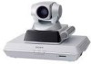
the video codec, audio codec, echo Terminal canceler, network interfaces and system controller. PCS-C1/C1P Camera Unit Composed of the camera and an integrated microphone. PCS-R1 Remote Commander Used to operate the Communication Terminal and Camera Unit. PCS-AC195 AC adaptor Supplies power - Sony PCS-1 | Operating Instructions - Page 13
or projector, etc. is required to monitor the images for videoconferencing system. Unit TV, Projector, etc. Description Used as a monitor and speakers. Chapter 1: Installation and Preparation Optional equipment especially designed for use with the PCS-1/1P The following optional devices are used - Sony PCS-1 | Operating Instructions - Page 14
Integrated microphone/speaker system suitable for remote communication. The uni-directional microphones pick up clear voice with minimum background noise. Moreover, the omni-directional speaker outputs sound equally in all directions. PCS-323M1 H.323 MCU Software PCS-320M1 H.320 MCU Software PCSA - Sony PCS-1 | Operating Instructions - Page 15
point-to-point videoconference over LAN. • To show still images stored in a "Memory Stick". System configuration 1 PCS-P1/P1P Communication Terminal 2 PCS-C1/C1P Camera Unit 3 PCS-R1 Remote Commander 4 TV monitor (not supplied) ON LINE POWER LAN ALERT ON LINE POWER LAN ALERT System Configuration 15 - Sony PCS-1 | Operating Instructions - Page 16
lines (when using the PCS-B768). System configuration 1 PCS-P1/P1P Communication Terminal 2 PCS-C1/C1P Camera Unit 3 PCS-R1 Remote Commander 4 TV monitor (not supplied) ON LINE POWER LAN ALERT * 5 PCS-B384 or PCS-B768 ISDN Unit (not supplied) * ON LINE POWER LAN ALERT * The illustration - Sony PCS-1 | Operating Instructions - Page 17
LAN ALERT ON LINE POWER LAN ALERT ON LINE POWER LAN ALERT ON LINE POWER LAN ALERT ON LINE POWER LAN ALERT 1 PCS-P1/P1P Communication Terminal 2 PCS-C1/C1P Camera Unit 3 PCS-R1 Remote Commander 4 TV monitor (not supplied) 5 PCS-323M1 H.323 MCU software (not supplied) System Configuration 17 - Sony PCS-1 | Operating Instructions - Page 18
LAN ALERT ON LINE POWER LAN ALERT ON LINE POWER LAN ALERT 1 PCS-P1/P1P Communication Terminal 2 PCS-C1/C1P Camera Unit 3 PCS-R1 Remote Commander 4 TV monitor (not supplied) 5 PCS-320M1 H.320 MCU software (not supplied) 6 PCS-B384 or PCS-B768 ISDN Unit (not supplied) The illustration shows an - Sony PCS-1 | Operating Instructions - Page 19
LAN ALERT ON LINE POWER LAN ALERT ON LINE POWER LAN ALERT 1 PCS-P1/P1P Communication Terminal 2 PCS-C1/C1P Camera Unit 3 PCS-R1 Remote Commander 4 TV monitor (not supplied) 5 PCS-323M1 H.323 MCU software (not supplied) 6 PCS-320M1 H.320 MCU software (not supplied) 7 PCS-B384 or PCS-B768 ISDN Unit - Sony PCS-1 | Operating Instructions - Page 20
ON LINE POWER LAN ALERT ON LINE POWER LAN ALERT 1 PCS-P1/P1P Communication Terminal 2 PCS-C1/C1P Camera Unit 3 PCS-R1 Remote Commander 4 TV monitor (not supplied) 5 PCS-323M1 H.323 MCU software (not supplied) 6 PCS-DSB1 Data Solution Box (not supplied) 7 PCS-A1 Microphone (not supplied) 20 System - Sony PCS-1 | Operating Instructions - Page 21
LINE POWER LAN ALERT 1 PCS-P1/P1P Communication Terminal 2 PCS-C1/C1P Camera Unit 3 PCS-R1 Remote Commander 4 TV monitor (not supplied) 5 PCS-320M1 H.320 MCU software (not supplied) 6 PCS-B384 or PCS-B768 ISDN Unit (not supplied) 7 PCS-DSB1 Data Solution Box (not supplied) 8 PCS-A1 Microphone (not - Sony PCS-1 | Operating Instructions - Page 22
. System Connection via a LAN PCS-C1/C1P Camera Unit TERMINAL VISCA OUT to TERMINAL PCS-P1/P1P Communication Terminal Camera cable* to CAMERA UNIT AUDIO OUT AUX1-VIDEO IN-AUX2 AUDIO IN (MIXED) VIDEO OUT AUX MAIN- MONITOR- SUB RGB OUT CAMERA UNIT MIC (PLUG IN POWER) 1 2 ISDN - Sony PCS-1 | Operating Instructions - Page 23
upgrade the software of the ISDN Unit. While the upgrading message is displayed on the monitor screen, be sure not to turn off the Communication Terminal. Doing so may cause malfunction of the system. PCS-C1/C1P Camera Unit TERMINAL VISCA OUT to TERMINAL PCS-P1/P1P Communication Terminal Camera - Sony PCS-1 | Operating Instructions - Page 24
Video Communication System can be controlled with the supplied Remote Commander. 1 Remove the battery compartment cover. 2 Insert two size AA (R6) batteries (supplied of batteries. • Do not attempt to charge the batteries. • If you do not intend to use the Remote Commander for a long period of time, - Sony PCS-1 | Operating Instructions - Page 25
a Sony TV, insert the IR repeater under the remote sensor of the TV. Once you set the IR repeater, the TV will turn on or go to standby together with the Communication Terminal when you press the "/1 button on the supplied Remote Commander. TV monitor CAMERA UNIT MIC (PLUG IN POWER) 1 2 ISDN - Sony PCS-1 | Operating Instructions - Page 26
, then only the POWER indicators on both units remain on in green. The launcher menu will appear on the monitor screen and the picture shot by the local camera will also appear in the launcher menu. Launcher menu Connect Phone Book Dial Menu Press to show help IP:0.0.0.0 Video:Main Angle Adj - Sony PCS-1 | Operating Instructions - Page 27
the software of the connected device. While the upgrading message is displayed on the monitor screen, be sure not to turn off the Communication Terminal. Doing so may cause malfunction of the system. System malfunction may also occur when a system power-off has been caused by an accidental problem - Sony PCS-1 | Operating Instructions - Page 28
lights in orange. The POWER indicator on the camera goes out. If the IR repeater is installed in a Sony TV monitor, it will go into standby together with the Video Communication System. Note When the Communication Terminal and the Camera are separately installed, point the Remote Commander to the - Sony PCS-1 | Operating Instructions - Page 29
for the videoconference. Note Set the power switch on the Communication Terminal off when the system will not be used for an extended period. While the power switch is off, you cannot receive a call from a remote party. Adjusting the Volume on the TV Monitor Before adjusting the volume on the TV - Sony PCS-1 | Operating Instructions - Page 30
Help Pressing the HELP button on the Remote Commander displays a balloon help or a help screen to guide most operations on the monitor screen. Note You can hide the balloon help used for entering characters. Press the MENU button on the Remote Commander to show the menu, select "Character Input Help - Sony PCS-1 | Operating Instructions - Page 31
Off VIDEO OUT Previous Next Cancel Dual Monitor: When two monitors are connected to the System, select whether you use the dual monitor mode to allow displaying motion pictures on one monitor. On: Enables the dual monitor mode. On the second monitor still images, images output from a computer or - Sony PCS-1 | Operating Instructions - Page 32
Remote Commander to select "Next", then press the PUSH ENTER button. The ISDN Setup Wizard appears when the PCS-B384 or PCS-B768 ISDN Unit is connected. When the ISDN Unit is not connected, the LAN Setup Wizard is displayed. Proceed to step 11 of the ISDN used by the system. When you use one ISDN - Sony PCS-1 | Operating Instructions - Page 33
the A1 and A2 boxes. When you use the PCS-B768 and connect 2 to 6 ISDN lines, enter manually. Host Name: Enter your host name. IP Address: Enter your IP address. Network Mask: Enter your network mask. Gateway Address: Enter your default gateway address. DNS Address: Enter your DNS (Domain Name System - Sony PCS-1 | Operating Instructions - Page 34
Using the Menu The Video Communication System uses the on-screen menus to make various adjustments basic operation through the menu is explained by taking the Setup menu. 1 Press the MENU button on the Remote Commander, or press the V, v, B or b button to select "Menu" and press the PUSH ENTER - Sony PCS-1 | Operating Instructions - Page 35
The menus of this system configure as described below. For more detailed menu configurations, refer to "Menu Configuration" on page 231. Launcher menu Connect Phone Book Dial Menu Press to show help IP:0.0.0.0 Video:Main Angle Adj. ISDN:012345678912 Audio:MIC(INT)+AUX Phone Book menu/Private - Sony PCS-1 | Operating Instructions - Page 36
show help IP:0.0.0.0 Video:Main Angle Adj. ISDN:012345678912 Audio:MIC(INT)+AUX The launcher menu appears when the Video Communication System is turned on or is displayed while it is not connected to a remote party. For details on the launcher menu, see pages 70 to 72. Phone Book menu Phone Book - Sony PCS-1 | Operating Instructions - Page 37
installed in the Communication Terminal. The menu Video/Audio system. The menu can be displayed by keeping the MENU button on the Remote conference. The menu appears when you select from the menu tabs displayed by selecting "Menu" in the launcher menu or by pressing the MENU button on the Remote - Sony PCS-1 | Operating Instructions - Page 38
Remote Commander. MIC an IP address Press HELP button on the Remote Commander to show balloon helps or help screens, you can hide only the balloon help used for entering characters. Select "Character Input Help" from the General Setup menu, then select "Off". (See page 47.) (dot) button HELP PCS - Sony PCS-1 | Operating Instructions - Page 39
the Administrator 1 Press the MENU button on the Remote Commander, or use the V, v, B or b button to select "MENU" in the launcher menu, then press the PUSH ENTER button. The initial Setup menu appears on the monitor screen. Setup Video/Audio Multipoint Mode Sound Priority Auto Keep pressing the - Sony PCS-1 | Operating Instructions - Page 40
IP: Connects a videoconferencing system via a LAN. ISDN: Connects a videoconferencing system via ISDN. ISDN (Telephone): Connects an audio-only telephone via ISDN (Voice Meeting). SIP: Connects an IP phone feature is available on the remote party. On: Always connects a remote party through BONDING. * - Sony PCS-1 | Operating Instructions - Page 41
Video Mode ALL Video Frame 15fps Audio Mode ALL Far End Camera Control On T.120 Data Off H.239 On Save Cancel Video Mode Selects the compression format of the pictures to be sent to a remote a computer picture is received with "Monitor Out" set to "RGB OUT", the number of video frame may - Sony PCS-1 | Operating Instructions - Page 42
audio based on the G.711 standard. Note When the remote videoconferencing system does not support the Audio Mode selected by the local site, the mode automatically switches to "G.711". Far End Camera Control When the conference starts by calling a remote party from the local site, selects whether to - Sony PCS-1 | Operating Instructions - Page 43
lists. User Name Input Before starting communication, selects whether you record the user names in the communication log. On: Records the user names. line is automatically connected. Off: Answers a call in manual answer mode. When you are called up, the phone rings. If you select "OK" for the message - Sony PCS-1 | Operating Instructions - Page 44
Note When the remote videoconferencing system does not support the Audio Mode selected by the local site, the mode automatically switches to "G.711". Far End Camera Control When the conference starts with a call from a remote party, selects whether to enable control of each other's cameras from each - Sony PCS-1 | Operating Instructions - Page 45
Name Dual Monitor Monitor Out Standby Mode Standby Time Time Display PCS-1ISDN Off VIDEO OUT On 30 minutes On Save Cancel Terminal Name Input the terminal name to report when the system is connected to the external multipoint videoconferencing system. Dual Monitor When two monitors are connected - Sony PCS-1 | Operating Instructions - Page 46
On: If the remote party has not yet been registered in the Phone Book, the message "Register this participant in the list?" appears on the monitor screen after the conference has finished. When you select "OK", the List Edit menu opens. Off: The above message does not appear. T.120 PC Address When - Sony PCS-1 | Operating Instructions - Page 47
only) Normally, select this mode. MODE 4: (For customers who are using the PCS-1P Video Communication System only) Select this mode if the System does not operate properly with the MODE 3 setting. Control by Far End When "Far End Camera Control" is set to "On" in the Dial Setup menu on the local - Sony PCS-1 | Operating Instructions - Page 48
: Inputs both sounds from the microphone and external equipment. Mic Select Selects the microphone to be used. Internal: Uses the built-in microphone. External: Uses the microphone connected to the Communication Terminal. DSB MIC: Uses the microphone connected to the Data Solution Box. CTE Selects - Sony PCS-1 | Operating Instructions - Page 49
of the speaker's lips is synchronized with his voice. Off: Disables the Lip Sync function. Recording Mute When connecting a video cassette recorder to the AUDIO IN/AUDIO OUT (MIXED) jacks to record the sound for a conference, the recording mute function prevents echo from reflecting on a remote site - Sony PCS-1 | Operating Instructions - Page 50
the default gateway address. DNS Address Enter the DNS (Domain Name System) address. 50 Registering Local Information Page 2/8 LAN Setup Page: 2/8 Gatekeeper Mode Off Gatekeeper Address User Alias User Number Save Cancel Gatekeeper Mode Sets whether you use the gatekeeper that controls - Sony PCS-1 | Operating Instructions - Page 51
Used Selects whether or not to fix the TCP port number and UDP port number. Custom: Uses the port numbers set by the user. Default: Uses the default port numbers, 2253 for the TCP port number and 49152 for the UDP port number. Registering Local Information 51 Chapter 2: Registration and Setup - Sony PCS-1 | Operating Instructions - Page 52
Port Numbers Used on the PCS-1/ 1P" on page 224. Page 6/8 LAN Setup Page: 6/8 TOS IP Precedence Low Delay High Throughput High Reliability Minimum Cost IP Precedence 0 Off Off Off Off Save Cancel TOS Selects how to define the TOS (Type of Service PPPoE User Name PPPoE Password Save Cancel - Sony PCS-1 | Operating Instructions - Page 53
super-user. The superuser password is valid to modify the items in the Phone Book menu. Remote Access Password Sets the password required to access this System from a Web browser. Accessing from a Web browser is also enabled by entering the administrator or superuser password. Web Monitor Selects - Sony PCS-1 | Operating Instructions - Page 54
whether or not to permit accessing the PCS-1/1P via a Web browser or Telnet. Disabled: Prohibits accessing via a Web browser or Telnet. Enabled: Permits accessing via a Web browser or Telnet. Page 2/2 Administrator Setup Page: 2/2 Save Phone Book Load Phone Book Auto Dialing On Create Private - Sony PCS-1 | Operating Instructions - Page 55
you connect. • The SPID menu does not appear depending on the protocol you selected on Page 1. Registering Local Information 55 Chapter 2: Registration and Setup for System Administrators - Sony PCS-1 | Operating Instructions - Page 56
ISDN switch type, configuration of SPID (Service Profile Identifier) is required. When you SPID" is not available in your area, set up SPID manually using the ISDN Setup menu. 1 Open the ISDN Setup "1*12". NTI DMS-100 (Custom ISDN): Enter "1*11". ISDN Setup Page: 1/7 Country/Region Country/Region - Sony PCS-1 | Operating Instructions - Page 57
the System has the optional PCS-320M1 H.320 MCU or PCS-323M1 H.323 MCU software installed Voice Activate: Detects the terminal with the speaker with the loudest voice, and sends the Selects the ISDN channels to be used for connecting the first remote point. 1B (64K): Connects via a 1B channel. 2B ( - Sony PCS-1 | Operating Instructions - Page 58
Mode ALL Audio Mode ALL Display Terminal Name On Far End Camera Control On Reject Answer Off Save Cancel ALL: Uses any video compression format depending on the format used on the remote sites. H.263: Uses pictures based on Recommendation H.263. H.261: Uses pictures based on Recommendation - Sony PCS-1 | Operating Instructions - Page 59
Option Option I/F Host Name IP Address MAC Address Serial Number VerX.XX VerX.XX VerX.XX VerX.XX Multipoint(H.323) DSB, ISDN UNIT PCS-1 0.0.0.0 00-00-00-00-00-00 12345 End Host Version Displays the software version of the Communication Terminal. ISDN UNIT Version Displays the version of the - Sony PCS-1 | Operating Instructions - Page 60
"Encode" show the setting status on the local system and those under "Decode" show the status on receiving. Status Page: 1/4 Communication Status (Encode) (Decode) Audio Mode G.728 G.728 Line I/F Connection A BRI Video Mode H.261CIF H.261CIF Camera Control ON Frame Rate 15fps 15fps Data - Sony PCS-1 | Operating Instructions - Page 61
Setup for System Administrators LAN bps 96016 bps 1622620 bps 1627056 bps Receive Packet Loss Audio Data Video Data Camera Control Data 0 / 7579 0 / 58085 0 / 2 0 % or a terminal with a different encryption password. You can start a conference without using the encryption feature with a - Sony PCS-1 | Operating Instructions - Page 62
IP phone using the SIP (Session Initiation Protocol). For details on a videoconference using SIP, see Chapter 9. Note The SIP Setup menu is available when the system has the optional PCSA-SP1 SIP software videoconference using SIP, enter the user name and password for each terminal. Page 3/3 - Sony PCS-1 | Operating Instructions - Page 63
IP phone using SIP. The List Edit menu switches according to the selected line interface. Note The "Line I/F" options differ depending on the software installed in the Communication Terminal. For a multipoint videoconference, see chapter 8. For SIP, see chapter 9. Registering a Remote Party - Phone - Sony PCS-1 | Operating Instructions - Page 64
in a "Memory Stick" to be registered in the Phone Book. Save Cancel 1 Enter the IP address of the remote party. Enter the host name and domain name when using registered in the Phone Book. To connect to the remote party without using BONDING If the videoconferencing system of the remote party is - Sony PCS-1 | Operating Instructions - Page 65
. Changing the Contents of the Phone Book You can change the telephone number, IP address, name or setting registered in the Phone Book. 1 Open the Phone Book menu. 2 Use the V, v, B or b button on the Remote Commander to select the remote party to be changed in the Phone Book menu, then press the - Sony PCS-1 | Operating Instructions - Page 66
of the lists simply by inserting the "Memory Stick". To register a new remote party in a Private Phone Book 1 Insert a "Memory Stick" in which you want to register a remote party into the Memory Stick slot on the Communication Terminal. Insert the "Memory Stick" in the direction of the arrow with - Sony PCS-1 | Operating Instructions - Page 67
Phone Book, how to delete the registered remote party, or how to copy the setting of the Private Phone Book are the same as those for the Phone Book. Open the Private Phone registered Private Phone Book into the Memory Stick slot on the Communication Terminal, then select "Delete Private Phone Book" - Sony PCS-1 | Operating Instructions - Page 68
IP Anne Jane Mary Anne 0.0.0.0 Recent 0-9 A-I J-S T-Z New Entry To exit from the Private Phone Book menu Remove the "Memory Stick" in which the Private Phone Book is registered from the Communication Terminal. The screen returns to the Phone Book menu. 68 Registering a Remote Party - Phone - Sony PCS-1 | Operating Instructions - Page 69
, you can begin talking just as with a normal phone call and start a videoconference. Turning on the Power 1 Turn on the TV monitor. When the IR repeater is inserted under the remote sensor of the Sony TV, set the TV to standby mode. When the power of the Communication Terminal is turned on, the TV - Sony PCS-1 | Operating Instructions - Page 70
local camera, local system status and buttons to open the menus. Connect Phone Book Dial Menu Press to show help IP:0.0.0.0 Video:Main Angle Adj. ISDN:012345678912 Audio:MIC(INT)+AUX 1 Screen The image shot by the local camera is displayed. 70 Starting a Conference by Calling a Remote Party - Sony PCS-1 | Operating Instructions - Page 71
the ISDN telephone number of the local system. telephone number Video: Video input The selected video input on the local system is shown. Main: Picture shot by the Camera Unit. Object: Picture shot by the optional PCS-DS150/ DS150P Document Stand. AUX1: Picture output from equipment connected to - Sony PCS-1 | Operating Instructions - Page 72
audio input on the local system is shown. MIC (INT): Sound from the built-in microphone. MIC (EXT): Sound from an external microphone connected to the Communication Terminal. MIC (DSB): Sound from an external microphone connected to the optional PCS-DSB1 Data Solution Box. MIC (AUX): Sound from an - Sony PCS-1 | Operating Instructions - Page 73
You can also display the menu by pressing the MENU button on the Remote Commander. The Setup menu appears. Setup Video/Audio Multipoint Mode Sound Priority Auto Keep pressing the [MENU] button to the settings in the More Options menu (page 65). Starting a Conference by Calling a Remote Party 73 - Sony PCS-1 | Operating Instructions - Page 74
screen. Dial IP Line I/F IP A2 LAN Bandwidth B1 1024 Kbps BC21 C2 More Options Dial Save Note Pressing the number buttons on the Remote Commander opens the Dial menu, allowing direct entry of the IP address or the ISDN telephone number with the number buttons. 74 Starting a Conference by - Sony PCS-1 | Operating Instructions - Page 75
to the H.221-format videoconferencing system via 2B channels of the ISDN connection. ISDN (Telephone): Connects to the phone of a remote party to conduct a voice meeting via the ISDN connection. 3 Configure the LAN, or ISDN line. When using the LAN Dial IP Line I/F IP A2 LAN Bandwidth B1 1024 - Sony PCS-1 | Operating Instructions - Page 76
IP address, press the DISPLAY (CLEAR) button on the Remote remote party to connect to in the A text box. Use the V, v, B or b button on the Remote Remote remote Remote Remote Commander. 2 Select the number of channels connected when setting up a call. Use the V, v, B or b button on the Remote remote - Sony PCS-1 | Operating Instructions - Page 77
address or ISDN telephone number entered in step 3. "Dialing (IP)" or "Dialing (ISDN)" appears on the monitor screen, and the ON LINE indicator (blue) on the Communication Terminal blinks. When the system connects to the remote system, the message "Meeting starts!" appears on the screen, and the ON - Sony PCS-1 | Operating Instructions - Page 78
Remote Commander to select "Phone Book" in the launcher menu, then press the PUSH ENTER button. The Phone Book menu appears on the monitor screen. Phone Book RECENT IP TOKYO Bob TOKYO 0.0.0.0 IP OSAKA ISDN NEW YORK John ISDN PARIS Recent 0-9 A-I J-S T-Z New Entry 78 Starting a Conference - Sony PCS-1 | Operating Instructions - Page 79
begins dialing the party selected in step 2. "Dialing (IP)" or "Dialing (ISDN)" appears on the monitor screen, and the ON LINE indicator (blue) on the Communication Terminal blinks. When the System connects to the system on the remote site, the message "Meeting starts!" appears on the screen, and - Sony PCS-1 | Operating Instructions - Page 80
press the CONNECT/DISCONNECT ( / ) button on the Remote Commander. The system dials the selected remote party. Note If the auto dialing feature of the Private Phone Book is activated, the system begins dialing when the "Memory Stick" is inserted. 80 Starting a Conference by Calling a Remote Party - Sony PCS-1 | Operating Instructions - Page 81
on the Remote Commander instead of the "0-9" tab on the Phone Book. Pressing the number button lists the six party names which start with the alphabetical letter on the number button of the Remote Commander. Chapter 3: Daily Videoconference Starting a Conference by Calling a Remote Party 81 - Sony PCS-1 | Operating Instructions - Page 82
manually before starting the conference. You can start it whenever you are ready. Notes • You cannot answer the call unless the power switch on the Communication Terminal is set to on (@). • Make sure that the TV monitor is turned on. If you insert the IR repeater under the remote sensor on the Sony - Sony PCS-1 | Operating Instructions - Page 83
in manual answer mode When you receive a call, the Communication Terminal rings and the message "Incoming call. Answer?" appears on the monitor screen. Press B or b to select "OK", then press the PUSH ENTER button. The system is then connected. Once the connection is made, the picture of the remote - Sony PCS-1 | Operating Instructions - Page 84
again. The system is disconnected. Note The power of the Communication Terminal remains on even if the system is disconnected. To cancel disconnection of the system Select "Cancel" with the B or b button, then press the PUSH ENTER button. To register the connected remote party in the Phone Book You - Sony PCS-1 | Operating Instructions - Page 85
be sent to the remote party. Press the MIC ON/OFF button on the Remote Commander. The sound of the local party is not heard by the remote party. The "MIC OFF" indicator appears on the monitor screen. MIC OFF To restore the sound Press the MIC ON/OFF button again. The "MIC OFF" indicator disappears - Sony PCS-1 | Operating Instructions - Page 86
party will be sent to the remote party when answering a call. The "MIC OFF" indicator appears on the monitor screen. To send the sound to the remote party Press the MIC ON/OFF button on the Remote Commander. Synchronizing Audio and Video - Lip Sync Function During the conference a time lag may occur - Sony PCS-1 | Operating Instructions - Page 87
obtain the desired angle and size. During communication you can also control the camera on the remote site to adjust the image shot by the remote camera. Selecting the Camera to be Controlled Before adjustment, choose whether you control the local or remote camera. 1 Press the FAR/NEAR button on - Sony PCS-1 | Operating Instructions - Page 88
monitor screen during communication and in the launcher menu when not in communication. You can also make adjustments using the Camera menu. To make adjustment during communication 1 Select the camera you want to adjust. Press the FAR/NEAR button on the Remote Commander to open the Display Control - Sony PCS-1 | Operating Instructions - Page 89
Videoconference Connect Phone Book Dial Menu Press to show help Angle Adj. Press the or button on the Remote Commander to adjust the camera angle. UPIPrsee:s0tsh.0teh.e0ZO.P0OUSMHbEutNtoTnEsRtobIzuSotDtoomNn:t0ion1ra2en3tud4r5on6utt7o.8th9e12 pVreidvieoous:Mscarienen. Audio:MIC(INT)+AUX - Sony PCS-1 | Operating Instructions - Page 90
Backlight On/Off. 3 While in communication, press the FAR/NEAR button on the Remote Commander to select the camera to be adjusted. When the remote camera is selected, the FAR indicator is displayed. Note When the remote camera is selected, only manual focus adjustment is available. 90 Adjusting the - Sony PCS-1 | Operating Instructions - Page 91
. You can also do so using the Camera menu. To preset the setting in the monitor screen while in communication 1 Select the camera whose camera angle and zoom setting you want to preset. Press the FAR/NEAR button on the Remote Commander to open the Display Control menu, then select "Far" or "Near - Sony PCS-1 | Operating Instructions - Page 92
PUSH ENTER button. The color of the screen frame changes, then you can adjust the camera angle and zoom. Camera Preset Save 1 Preset Load 2 Adjustments 3 4 5 6 4 While in communication, select the camera to be adjusted with the FAR/ NEAR button on the Remote Commander. 92 Adjusting the - Sony PCS-1 | Operating Instructions - Page 93
recall the preset setting in the monitor screen while in communication 1 Select the camera which you want to move to the preset position. Press the FAR/NEAR button on the Remote Commander to open the Display Control menu, then select "Far" or "Near" under "Control". 2 Press one of the number buttons - Sony PCS-1 | Operating Instructions - Page 94
. Camera Preset Save Preset Load Adjustments 1 2 3 4 5 6 Use the following Remote Commander buttons to adjust the camera. camera adjustments even if the Communication Terminal is turned off. Notes • The built-in lithium battery is kept charged as long as the system is operated. If the system - Sony PCS-1 | Operating Instructions - Page 95
to select "Near" or "Far" under "Display". Display Control Display Control Far Near Camera 3 Press the PUSH ENTER button on the Remote Commander. Selecting the Input Picture 1 Press the VIDEO INPUT SELECT button on the Remote Commander. The Video Input Select menu appears. 2 Use the V, v, B or - Sony PCS-1 | Operating Instructions - Page 96
communication you can switch the video input of the remote system by selecting "Far" in the Video Input Select menu. Video Input Select Near Far DSB Input Main Main RGB A Main: Select the picture shot by the Camera. Object: Select the picture from the optional PCS-DS150/DS150P Document Stand - Sony PCS-1 | Operating Instructions - Page 97
Signal from the Connected Equipment for a Conference" on page 136 and "Video conference Using a Whiteboard" on page 144. Switching the Sound to Be Sent to the Remote Party You can switch the sound sent to the remote party between the sound from the microphone and that from the connected equipment - Sony PCS-1 | Operating Instructions - Page 98
as a Window Picture - PinP Feature You can display the picture shot by the local camera on your monitor screen as a window picture (Picture-in-Picture). This function enables you to check how your own party is monitored on the remote site. To display the window picture Press the PinP button on the - Sony PCS-1 | Operating Instructions - Page 99
the optional equipment in addition to the components contained in the PCS-1/1P Video Communication System. To conduct a data conference using the optional PCS-DSB1 Data Solution Box, see Chapter 5. To conduct a multipoint conference, see Chapter 8. Using Still Images Stored in a "Memory Stick" for - Sony PCS-1 | Operating Instructions - Page 100
button. The menu disappears and the selected still image is displayed on the monitor screen. To clear the still image from the monitor screen While the still image is displayed, press the PUSH ENTER button on the Remote Commander. The Memory Stick menu is restored. Viewing a slide show You can view - Sony PCS-1 | Operating Instructions - Page 101
the PUSH ENTER button. The slide show starts. During communication with a remote party, the still images are transmitted to the remote party. The indicator is displayed on the monitor screen during the slide show. 4 Press the b button on the Remote Commander to advance a slide. Pressing the B button - Sony PCS-1 | Operating Instructions - Page 102
communication, you can send still images stored in a "Memory Stick" to the remote party. 1 Insert a "Memory Stick" into the Memory Stick slot on the Communication , and is sent to the remote party. The message "The still image has been sent." appears on the monitor screen. When you select "Slide - Sony PCS-1 | Operating Instructions - Page 103
Chapter 4: Videoconference With Optional Equipment For details on a slide show, see page 100. Note The image file to be sent will be saved to the directory "\DCIM\100MSDCF". Using Still Images Stored in a "Memory Stick" for a Videoconference 103 - Sony PCS-1 | Operating Instructions - Page 104
Because it is removable, "Memory Stick" can also be used for external data storage. "Memory Stick" is available in two sizes: standard MagicGate Memory Stick" with the unit. However, because the unit does not support the MagicGate standards, data recorded with the unit is not subject to MagicGate - Sony PCS-1 | Operating Instructions - Page 105
than the supplied label onto car parked in the sun. - under computer cannot be guaranteed on the Communication Terminal. Make sure to use a "Memory Stick" that has been formatted with the Communication Terminal. • If you format a "Memory Stick", all data, including the still images and Phone - Sony PCS-1 | Operating Instructions - Page 106
You can send motion pictures shot by the Camera or those output from the connected external equipment as still images. When you are Images Using the Still Image Menu While in communication with the remote party, you can send motion pictures shot by the local camera as still images. You can send one - Sony PCS-1 | Operating Instructions - Page 107
Submenu You can easily send only one image displayed on the monitor screen as a still image during communication. 1 Press the PUSH ENTER button on the Remote Commander during communication. The Communication submenu appears. Send Save Presentation START Whiteborad ON Icon Display OFF - Sony PCS-1 | Operating Instructions - Page 108
a still image to the remote party. PCS-DS150/DS150P Document Stand (not supplied) To send a still image 1 Shoot the image you want to send with the Document Stand. For details how to operate the Document Stand, refer to the Operating Instructions supplied with the Document Stand. 2 Open the Still - Sony PCS-1 | Operating Instructions - Page 109
to the Communication Terminal can be frozen, and then sent to the remote party. Chapter 4: Videoconference With Optional Equipment External camera, VCR, etc. AUDIO OUT AUX1-VIDEO IN-AUX2 AUDIO IN (MIXED) VIDEO OUT AUX MAIN- MONITOR- SUB RGB OUT CAMERA UNIT MIC (PLUG IN POWER) 1 2 XXXX - Sony PCS-1 | Operating Instructions - Page 110
Remote Party During communication you can receive still images of the pictures shot by the remote camera if "Far End Camera Control the FAR/NEAR button on the Remote Commander. The picture shot by the remote camera and the FAR indicator appear on the monitor screen in the Still Image menu window - Sony PCS-1 | Operating Instructions - Page 111
picture shot by the local camera or input picture from the connected equipment or the remote picture during conference in a "Memory Stick". on the monitor screen. To switch the input on the local site, press the VIDEO INPUT SELECT button on the Remote Commander to display the Video Input Select - Sony PCS-1 | Operating Instructions - Page 112
with a file name as "DSCXXXXX.JPG". Compression format The Communication Terminal compresses and records the recorded image data in the JPEG the input on the local site, press the VIDEO INPUT SELECT button on the Remote Commander to display the Video Input Select menu, select the desired picture, - Sony PCS-1 | Operating Instructions - Page 113
Submenu You can promptly save the picture displayed on the monitor screen during communication to the "Memory Stick" as a still image. 1 During communication with the remote party press the PUSH ENTER button. The communication submenu appears. Send Save Presentation START Whiteboard ON Icon - Sony PCS-1 | Operating Instructions - Page 114
camera. Save: Saves the picture displayed on the monitor screen to a "Memory Stick" as a still picture. Presentation START: Sends the RGB picture input from the optional PCSDSB1 Data Solution Box to a remote when the MCU software has been installed in the Communication Terminal. After selecting - Sony PCS-1 | Operating Instructions - Page 115
OUT 2 Under the remote sensor IR repeater (supplied) to S-video input Signal cable (not supplied) S-video connecting cable (not supplied) Second monitor (projector, etc.) Activating dual monitor system Set "Dual Monitor" to "On" in Page 1 of the General Setup menu. The default setting is "Off - Sony PCS-1 | Operating Instructions - Page 116
to the VIDEO OUT MONITOR SUB connector on the Communication Terminal. RGB OUT: Outputs a signal to the monitor connected to the RGB OUT connector on the Communication Terminal. To view the picture as a window picture When you press the PinP button on the Remote Commander during communication, the - Sony PCS-1 | Operating Instructions - Page 117
NEAR button on the Remote Commander to display the Display Control menu, then select "Far" (remote party) or "Near" (local party) under "Display". Second monitor • Enables display of motion pictures on the local site, a still image received or transmitted, an RGB image via the PCS-DSB1 Data Solution - Sony PCS-1 | Operating Instructions - Page 118
AUX MAIN- MONITOR- SUB RGB OUT CAMERA UNIT MIC (PLUG IN POWER) 1 2 ISDN UNIT WHITE BOARD IR OUT 1 2 100BASE-TX 10BASE-T DSB DC 19.5V to MIC 1 to MIC 2 PCS-A1 (not supplied) or PCS-A300 microphone (not supplied) To use the connected microphone Set "Mic Select" to "External" in the - Sony PCS-1 | Operating Instructions - Page 119
Microphone layout examples Microphone built in the PCS-1/1P PCS-1/1P PCS-A300 microphones PCS-A300 PCS-1/1P Chapter 4: Videoconference With Optional Equipment PCS-A1 microphones PCS-A1 PCS-1/1P Using Multiple Microphones 119 - Sony PCS-1 | Operating Instructions - Page 120
MAIN- MONITOR- SUB RGB OUT CAMERA UNIT MIC (PLUG IN POWER) 1 2 ISDN UNIT WHITE BOARD IR OUT 1 2 100BASE-TX 10BASE-T DSB DC 19.5V to AUDIO IN AC adaptor (supplied with the CTE-600 ) Connecting cable (not supplied) to a wall outlet to AUDIO OUT To use the Communication Transducer - Sony PCS-1 | Operating Instructions - Page 121
CTE layout example PCS-1/1P CTE-600 Chapter 4: Videoconference With Optional Equipment Using the Communication Transducer (CTE) 121 - Sony PCS-1 | Operating Instructions - Page 122
for taking minutes of the conference. To connect a video cassette recorder Video cassette recorder, etc. to audio input TERMINAL VISCA OUT AUDIO OUT AUX1-VIDEO IN-AUX2 AUDIO IN (MIXED) VIDEO OUT AUX MAIN- MONITOR- SUB RGB OUT CAMERA UNIT MIC (PLUG IN POWER) 1 2 ISDN UNIT WHITE BOARD - Sony PCS-1 | Operating Instructions - Page 123
The Communication Terminal is equipped with two video inputs. VCR, etc. to S-video output to VIDEO IN AUX 1 S-video connecting cable (not supplied) TERMINAL VISCA OUT AUDIO OUT AUX1-VIDEO IN-AUX2 AUDIO IN (MIXED) VIDEO OUT AUX MAIN- MONITOR- SUB RGB OUT CAMERA UNIT MIC (PLUG IN POWER - Sony PCS-1 | Operating Instructions - Page 124
When set to "AUX", the sound from the external equipment is input and the sound from a microphone is deactivated. When set to "MIC + AUX", both sounds are input. 124 Sending Audio/Video from the External Equipment to a Remote Party - Sony PCS-1 | Operating Instructions - Page 125
To connect the external video equipment for output VCR, etc. to Video input Video connecting cable (not supplied) Projector, etc. TERMINAL VISCA OUT AUDIO OUT AUX1-VIDEO IN-AUX2 AUDIO IN (MIXED) VIDEO OUT AUX MAIN- MONITOR- SUB RGB OUT CAMERA UNIT MIC (PLUG IN POWER) 1 2 ISDN UNIT - Sony PCS-1 | Operating Instructions - Page 126
Using the PCS-1/1P Video Communication System, you can conduct a conference only through voices via a normal phone without connecting the videoconferencing system. (Voice Meeting) Basic connecting procedures are the same as those for videoconferencing. Conducting a voice meeting with a remote party - Sony PCS-1 | Operating Instructions - Page 127
The Video Communication System enables you to control the remote system connected by transmitting the tone signal (DTMF: Dual Tone Multi Frequency) assigned to the numbers for dialing (0-9, , ). 1 Press the button on the Remote Commander during communication. The DTMF menu appears on the monitor - Sony PCS-1 | Operating Instructions - Page 128
) VIDEO OUT AUX MAIN- MONITOR- SUB RGB OUT CAMERA UNIT MIC (PLUG IN POWER) 1 2 ISDN UNIT WHITE BOARD IR OUT 1 2 100BASE-TX 10BASE-T DSB DC 19.5V to 100BASE-TX/ 10BASE-T UTP cross cable (not supplied) to LAN connector Computer Computer 128 Conducting a Data Conference Using - Sony PCS-1 | Operating Instructions - Page 129
MAIN- MONITOR- SUB RGB OUT CAMERA UNIT MIC (PLUG IN POWER) 1 2 ISDN UNIT WHITE BOARD IR OUT 1 2 100BASE-TX 10BASE-T DSB DC 19.5V to 100BASE-TX/ 10BASE-T UTP straight cable (not supplied) To configure the Communication Terminal Open Page 2 of the General Setup menu, and enter the IP - Sony PCS-1 | Operating Instructions - Page 130
window on the computer of either a local or remote party. 4 Enter the IP address set for the Communication Terminal in the "Address" text box of the "Call to" dialog box. 5 Click "Call". After a while the connection is completed. For details on how to operate, refer to the Help menu of the - Sony PCS-1 | Operating Instructions - Page 131
in the Administrator Setup Menu (page 54). For details on the password to access or Web monitoring feature, see "Administrator Setup Menu" on page 53. Using Telnet Accessing the IP address of the Communication Terminal from Telnet allows you to control or set up the Terminal. To permit accessing the - Sony PCS-1 | Operating Instructions - Page 132
a remote party. When you connect a projector, you can display a highresolution image from a computer on the projector at a high transmission rate. The PCS-DSB1 is also equipped with connectors for connecting active speakers and microphones. The PCS-DSB1 is connected with the Communication Terminal - Sony PCS-1 | Operating Instructions - Page 133
Box. While the upgrading message is displayed on the monitor screen, be sure not to turn off the Communication Terminal. Doing so may cause malfunction of the system. PCS-C1/C1P Camera Unit PCS-P1/P1P Communication Terminal ON LINE POWER LAN ALERT Interface cable (supplied with to DSB the - Sony PCS-1 | Operating Instructions - Page 134
PCS-P1/P1P Communication Terminal, but the computer picture while transmitting cannot be output from these connectors. Notes on the connection of a microphone • Up to five microphones can be connected with the Data Solution Box. • When using external microphones, the sound transmitted to the remote - Sony PCS-1 | Operating Instructions - Page 135
to "PCS". Note You cannot use two or more Communication Transducers in a room and cannot use it with other microphones together. For detailed information on the Communication Transducer, refer to the Operating Instructions that come with the Communication Transducer. Chapter 5: Data Conference - Sony PCS-1 | Operating Instructions - Page 136
Connected Equipment for a Conference Setting Before Conferencing To use a microphone connected to the Data Solution Box Set "Mic Select" to "DSB MIC" in the Audio Setup menu (page 48). To use a projector, etc. connected to the RGB OUT connector on the Data Solution Box Set "Monitor Out (or Sub - Sony PCS-1 | Operating Instructions - Page 137
button or the VIDEO INPUT SELECT button is displayed on the projector, etc. connected to the RGB OUT connector on the Data Solution Box. While in communication, the picture selected on the Data Solution Box is transmitted to the remote party simultaneously. Such computer picture is displayed without - Sony PCS-1 | Operating Instructions - Page 138
H.323 (for LAN) or PCS-320M1 H.320 (for ISDN) MCU software, you can transmit the picture from the computer to multiple points. Picture quality of the data solution box The picture quality received by the remote party varies depending on the type of the terminal or connecting method, or "Monitor Out - Sony PCS-1 | Operating Instructions - Page 139
the PCS-1/1P is used as a receiving terminal Setting of "Monitor Out (or Sub Monitor Out)" on the receiving terminal When "Dual Monitor" is set to "Off" When "Dual Monitor" is set to "On" Output connector for a computer picture on receiving terminal Resolution VIDEO - OUT VIDEO OUT a MONITOR - Sony PCS-1 | Operating Instructions - Page 140
Monitor" is set to "On" Output connector for a computer picture on receiving terminal Resolution Video frame rate Picture quality RGB OUT (DSB) RGB OUT (DSB) RGB OUT on the PCS-DSB1 (only when the PCS a: Middle, f: Low 140 Using Audio/Video Signal from the Connected Equipment for a Conference - Sony PCS-1 | Operating Instructions - Page 141
When videoconferencing system other than the PCS-1/1P and PCS-11/11P such as the PCS-1600 is used Resolution a Video frame rate f Remarks Sends and receives the seconds is obtained. : High, a: Middle, f: Low Chapter 5: Data Conference Using Audio/Video Signal from the Connected Equipment for - Sony PCS-1 | Operating Instructions - Page 142
external monitors, etc. using the following four outputs are available. The connections allow output of the picture to one or two monitors selected from among four. Monitor A Monitor B to VIDEO OUT MONITOR MAIN ON LINE POWER LAN ALERT to VIDEO OUT MONITOR SUB to RGB OUT to RGB OUT on the PCS - Sony PCS-1 | Operating Instructions - Page 143
the VIDEO OUT MONITOR SUB connector is not available. When connecting the monitor to the RGB OUT connector on the Data Solution Box The menus may not be displayed. In this case, change the setup of your system as described below. 1 Connect your monitor to the RGB OUT connector on the Communication - Sony PCS-1 | Operating Instructions - Page 144
of the United States. Note Videoconferencing using the whiteboard is available only between systems equipped with the PCS-1/1P or when a receiving terminal is PCS-G70/G70P or PCS-11/11P. You cannot use this function with other Sony videoconferencing systems such as PCS1600, or other manufacturers - Sony PCS-1 | Operating Instructions - Page 145
VISCA OUT AUDIO OUT AUX1-VIDEO IN-AUX2 AUDIO IN (MIXED) VIDEO OUT AUX MAIN- MONITOR- SUB RGB OUT CAMERA UNIT MIC (PLUG IN POWER) 1 2 ISDN UNIT WHITE BOARD IR OUT 1 2 100BASE-TX 10BASE-T DSB DC 19.5V to WHITE BOARD Dedicated cable (supplied with the mimio Xi) Whiteboard - Sony PCS-1 | Operating Instructions - Page 146
Attaching the mimio Xi on the Whiteboard Attach the mimio Xi at the upper left corner of a whiteboard vertically or horizontally, then set the attachment orientation of the mimio Xi and the size of the whiteboard using the menu. Vertically Horizontally To set the attachment orientation of the - Sony PCS-1 | Operating Instructions - Page 147
ALERT LAN or ISDN ON LINE POWER LAN ALERT 1 Start the videoconference. 2 When you intend to send the whiteboard picture, press the PUSH ENTER button on the Remote Commander to display the communication submenu on the monitor screen. Communication submenu Send Save Presentation START Whiteborad - Sony PCS-1 | Operating Instructions - Page 148
"Far End Camera Control" in the Answer Setup menu (page 44) to "On". The whiteboard cannot be used for a videoconference unless these items are set to "On" for all the participating terminals. • If a party participates in the middle of the multipoint conference using a whiteboard, the monitor of the - Sony PCS-1 | Operating Instructions - Page 149
To exit from the whiteboard mode The whiteboard user should open the communication submenu, select "Whiteboard OFF", then press the PUSH ENTER button. The pictures displayed on the monitors of all the terminals switch to the normal camera pictures. Under this circumstance, any terminal may select - Sony PCS-1 | Operating Instructions - Page 150
the cascade connection via LAN). Note In an encrypted conference only video signals, audio signals and RGB signals from a computer connected to the Data Solution Box are encrypted. Camera control signals (for controlling the other party's camera) and whiteboard pictures cannot be encrypted. 150 - Sony PCS-1 | Operating Instructions - Page 151
equipped with the encryption feature to a terminal with "Encryption via LAN" set to "Off", or to a terminal without the same password as that of your system. • You can conduct a videoconference without an encryption feature with a terminal connected via an ISDN even if you set "Encryption via LAN - Sony PCS-1 | Operating Instructions - Page 152
. Error Messages Causes The encryption feature on a far- The encryption feature via LAN on the remote end system is disabled. system is disabled. The entered password for the The password entered on the remote system is encryption feature is not correct. not the same as that on the local - Sony PCS-1 | Operating Instructions - Page 153
installation of the optional PCS-323M1 MCU software (for LAN connection) based on the H.323 standard or the optional PCS-320M1 MCU software (for ISDN connection) are up to 12B. • The supported video modes are H.263 and H.261 only. • The supported audio modes are G.711, G.722 and G.728 only. 153 - Sony PCS-1 | Operating Instructions - Page 154
fly" feature). ON LINE POWER LAN ALERT PCS-323M1 H.323 MCU ON LINE POWER LAN ALERT software TERMINAL VISCA OUT ON LINE POWER LAN ALERT AUDIO OUT AUX1-VIDEO IN-AUX2 AUDIO IN CAMERA UNIT MIC (PLUG IN POWER) 1 2 ISDN UNIT WHITE BOARD (MIXED) VIDEO OUT AUX MAIN- MONITOR- SUB RGB OUT - Sony PCS-1 | Operating Instructions - Page 155
TERMINAL VISCA OUT to LAN PCS-323M1 H.323 MCU software ON LINE POWER LAN ALERT AUDIO OUT AUX1-VIDEO IN-AUX2 AUDIO IN CAMERA UNIT MIC (PLUG IN POWER) ISDN UNIT WHITE ON LINE POWER LAN ALERT 1 2 BOARD ON LINE POWER LAN ALERT (MIXED) VIDEO OUT AUX MAIN- MONITOR- SUB RGB OUT IR OUT - Sony PCS-1 | Operating Instructions - Page 156
optional PCS-B384 or PCS-B768 ISDN Unit. PCS-320M1 H.320 MCU software The illustration shows an example using the PCS-B768 ISDN Unit. TERMINAL VISCA OUT AUDIO OUT AUX1-VIDEO IN-AUX2 AUDIO IN (MIXED) VIDEO OUT AUX MAIN- MONITOR- SUB RGB OUT CAMERA UNIT MIC (PLUG IN POWER) 1 2 ISDN - Sony PCS-1 | Operating Instructions - Page 157
setting on the remote party's terminal has priority. To connect with a normal phone When you are using an ISDN connection, a normal phone can be connected at normal phone. Notes • When using the ISDN connections, installing the PCS-320M1 H.320 MCU software into two or more Communication Terminals - Sony PCS-1 | Operating Instructions - Page 158
a LAN and ISDN. PCS-323M1 H.323 and PCS-320M1 H.320 MCU software The illustration shows an example using the PCS-B768 ISDN Unit. TERMINAL VISCA OUT AUDIO OUT AUX1-VIDEO IN-AUX2 AUDIO IN (MIXED) VIDEO OUT AUX MAIN- MONITOR- SUB RGB OUT CAMERA UNIT MIC (PLUG IN POWER) 1 2 ISDN UNIT - Sony PCS-1 | Operating Instructions - Page 159
-323M1 H.323 and PCS-320M1 H.320 MCU software in two Communication Terminals enables cascade connection including two main terminals. Connecting four terminals to one main terminal allows you to conduct a multipoint videoconference via a LAN and ISDN among up to ten points. LAN* ON LINE POWER LAN - Sony PCS-1 | Operating Instructions - Page 160
which is copied to another Memory Stick with a computer, etc. 1 Set the power switch on the right side of the Communication Terminal to the off position (a). 2 Insert the "Memory Stick" containing the PCS-323M1 or PCS-320M1 MCU software into the Memory Stick slot. Insert the "Memory Stick" in - Sony PCS-1 | Operating Instructions - Page 161
menu when "Multipoint Mode" is set to "On". Connect Phone Book Dial Menu Press to show help IP:0.0.0.0 Video:Main Angle Adj. ISDN:012345678912 Audio:MIC(INT)+AUX Multipoint mode icon The installed software will be shown in "Software Option" of the Machine Information menu. For details on the - Sony PCS-1 | Operating Instructions - Page 162
Select "Multipoint Mode" to " On" or "Auto". The other items for a multipoint videoconference can be set in the Multipoint Setup menu. Setup Video/Audio Multipoint Mode Sound Priority On Keep pressing the [MENU] button to show more detailed setup menus. Save Cancel Multipoint Mode On: Always - Sony PCS-1 | Operating Instructions - Page 163
Lines Total LAN Bandwidth Restrict IOSnDN Split 2B (128K) 1024 Kbps Auto Save Cancel Multipoint Setup Page: 2/2 Video Mode ALL Audio Mode ALL Display Terminal Name On Far End Camera Control On Reject Answer Off Save Cancel For details on the setting of the items, see "Multipoint Setup - Sony PCS-1 | Operating Instructions - Page 164
"New Entry" in the Phone Book menu to display the List Edit menu, then enter the name of the multipoint connection list in the Index text box. For details on entry, see steps 1 to 3 "Registering a New Remote Party" on page 63. List Edit Index MULTILIST IP IP Line I/F IP LAN Bandwidth 1024 Kbps - Sony PCS-1 | Operating Instructions - Page 165
parties to be connected for a multipoint conference. To register a normal phone, enter the telephone number with "T" at the beginning. (e.g., T0312345678) List Edit Index MULTILIST2 A B C D E IP ISDN IP IP Line I/F IP&ISDN IP LAN Bandwidth IP 1024 Kbps IP Number of Lines 6 B (384K) Save - Sony PCS-1 | Operating Instructions - Page 166
", then press the PUSH ENTER button. Phone Book RECENT IP TOKYO Bob IP OSAKA PARIS 0.0.0.0 ISDN NEW YORK John IP PARIS Recent 0-9 A-I J-S T-Z On Dial Edit Copy Delete The (multipoint) mark is added to the upper left of the selected name in the list and the remote party is registered in the - Sony PCS-1 | Operating Instructions - Page 167
marked with are entered in the number text boxes. List Edit Index A 123.123.123.123 B 123.123.123.124 C 123.123.123.125 D E IP Line I/F IP LAN Bandwidth 1024 Kbps Save Cancel 5 Enter the name of the multipoint connection list in the Index text box. 6 Select "Save", then press the PUSH - Sony PCS-1 | Operating Instructions - Page 168
registered in the multipoint connection list. " Dialing (IP)", " Dialing (ISDN)" or "Dialing ( IP & ISDN)" appears on the monitor screen, and the ON LINE indicator (blue) on the Communication Terminal blinks. When the system connects to all the remote points, the message "Meeting starts!" appears on - Sony PCS-1 | Operating Instructions - Page 169
Chapter 8: Multipoint Videoconference 2 Press the button on the Remote Commander, or press the PUSH ENTER button to open the submenu, press the V or v button to select " On", then press the PUSH ENTER button. Phone Book RECENT IP TOKYO Bob IP OSAKA PARIS 1234567 ISDN NEW YORK John ISDN PARIS - Sony PCS-1 | Operating Instructions - Page 170
remote party with the marks. " Dialing (IP)", " Dialing (ISDN)" or " Dialing (IP & ISDN)"appears on the monitor screen, and the ON LINE indicator (blue) on the Communication Terminal blinks. When the system -point conference. For details, see "To call a remote party not registered in the Phone Book" - Sony PCS-1 | Operating Instructions - Page 171
dialing the numbers selected in step 3. " Dialing (IP)", " Dialing (ISDN)" or " Dialing (IP & ISDN)" appears on the monitor screen, and the ON LINE indicator (blue) on the Communication Terminal blinks. When the system connects to all the remote parties, the message "Meeting starts!" appears on the - Sony PCS-1 | Operating Instructions - Page 172
item. Some Positions were not connected. Status ABCDE Cause Code XX YY Start Meeting Disconnect All Redial Start Meeting: Starts a conference with remote parties connected. Disconnect All: Cancels all the connections and restores the launcher menu. Redial: Redials the numbers of the points - Sony PCS-1 | Operating Instructions - Page 173
picture of a specified terminal is shown in full screen during communication, the location of Pictures A to E will be changed when the Split mode is restored. • When your system is in the Split or Split (Fixed) mode, you cannot control the camera on any connected remote terminals. Using the Display - Sony PCS-1 | Operating Instructions - Page 174
pictures from the connected remote terminals and the picture of the local terminal are displayed by splitting the monitor screen as the same manner in this window. Voice Activate mode Detects the terminal with the speaker with the loudest voice among the connected terminals, and displays the Control - Sony PCS-1 | Operating Instructions - Page 175
below shows the window displayed on the monitor screen when you select one of the Broadcast Modes. According to the connection status of your system, some modes cannot be selected. In - connected Voice Activate Full screen Full screen Broadcast Full screen - Using the Display Control 175 - Sony PCS-1 | Operating Instructions - Page 176
the Broadcast Mode At the beginning of the conference the mode set with "Broadcast Mode" in the Multipoint Setup menu is activated. You can switch the mode during communication. 1 Press the FAR/NEAR button on the Remote Commander. The Display Control menu appears. 2 Use the V, v, B or b button on - Sony PCS-1 | Operating Instructions - Page 177
the system returns to the previous mode. Notes • If you have received "Self Broadcast" command from another terminal, the operation above will not be carried out. • When you use a cascade connection, the Video Communication System supports the Voice Activate mode only. Using the Display Control 177 - Sony PCS-1 | Operating Instructions - Page 178
Ending the Multipoint Videoconference 1 Press the CONNECT/DISCONNECT ( Commander. The following submenu appears. / ) button on the Remote Disconnect Phone Book Dial Cancel 2 Use the V, v, B or b button to select "Disconnect", then press the PUSH ENTER button. The screen changes to the split - Sony PCS-1 | Operating Instructions - Page 179
"Off" are mixed As the bit rate of video signals differs depending on the setting of "Far End Camera Control", the picture is not displayed on some terminals. When a 56K network is mixed among the terminals if the conference is held via 64K network The conference automatically changes to that via 56 - Sony PCS-1 | Operating Instructions - Page 180
multipoint videoconference unless the MCU software is installed into the Communication Terminal. MCU LAN or ISDN ON LINE POWER LAN ALERT ON LINE POWER LAN ALERT ON LINE POWER LAN ALERT ON LINE POWER LAN ALERT ON LINE POWER LAN ALERT PCS-1/1P Activating the Chair Control If the MCU for the - Sony PCS-1 | Operating Instructions - Page 181
incorrectly, the message "MCU operation rejected." will appear on the monitor screen. Displaying the picture of the selected terminal 1 Open the Display Control menu. 2 Use the V, v, B or b button to select all terminals. The indicator is shown on the monitor screen. Connecting the External MCU 181 - Sony PCS-1 | Operating Instructions - Page 182
Exiting the chair control 1 Open the Display Control menu. 2 Use the V, v, B or b button to select "Chair Release" under "Broadcast Mode". The chair control is not available for the local party. 182 Connecting the External MCU - Sony PCS-1 | Operating Instructions - Page 183
/six-split/user control 7.2 video algorithm at each port H.261, H.263 H.261, H.263 8 Data Processor Equipped Equipped 8.1 data broadcast facility, LSD Equipped - data broadcast facility, HSD No - 8.2 MLP Processor Equipped - 9 Encryption No support Support Multipoint Attribute - Sony PCS-1 | Operating Instructions - Page 184
/receiving only via a normal phone. Capable of audio sending/receiving and video receiving only. Capable of audio sending/receiving only via a normal phone. 12 Call setup provision(s) No call/receive reservation No call/receive reservation 13 Control capabilities - - 13.1 Numbering of - Sony PCS-1 | Operating Instructions - Page 185
with up to 5 IP phones. Restrictions on the use of the SIP software • The settings of the Setup menu are invalid for SIP connection. • Data transmission via the Data Solution Box is not possible during a videoconference using SIP. • The remote camera cannot be controlled during a videoconference - Sony PCS-1 | Operating Instructions - Page 186
has been installed to an IP phone and a SIP server via a hub. PCS-1/1P SIP server PCSA-SP1 SIP software TERMINAL VISCA OUT AUDIO OUT AUX1-VIDEO IN-AUX2 AUDIO IN (MIXED) VIDEO OUT AUX MAIN- MONITOR- SUB RGB OUT CAMERA UNIT MIC (PLUG IN POWER) 1 2 ISDN UNIT WHITE BOARD IR OUT - Sony PCS-1 | Operating Instructions - Page 187
is also enabled. SIP server PCSA-SP1 PCS-323M1 PCS-1/1P Hub LAN TERMINAL VISCA OUT to LAN to LAN IP phone AUDIO OUT AUX1-VIDEO IN-AUX2 AUDIO IN (MIXED) VIDEO OUT AUX MAIN- MONITOR- SUB RGB OUT CAMERA UNIT MIC (PLUG IN POWER) 1 2 ISDN UNIT WHITE BOARD IR OUT 1 2 100BASE - Sony PCS-1 | Operating Instructions - Page 188
AUDIO IN (MIXED) VIDEO OUT AUX MAIN- MONITOR- SUB RGB OUT CAMERA UNIT MIC (PLUG IN POWER) 1 2 ISDN UNIT WHITE BOARD IR OUT 1 2 100BASE-TX 10BASE-T DSB DC 19.5V to 100BASE-TX/ 10BASE-T to LAN UTP cable (category 5, straight) (not supplied) to LAN LAN IP phone to LAN PCSASP1 - Sony PCS-1 | Operating Instructions - Page 189
to "LOCK". • Once the SIP software is installed in the Communication Terminal, the software will not be used again. • You cannot install the SIP software which is copied to another "Memory Stick" with a computer, etc. 1 Set the power switch on the right side of the Communication Terminal to the off - Sony PCS-1 | Operating Instructions - Page 190
Machine Information menu. Machine Information Host Version ISDN UNIT Version DSB Version DSP Version Software Option Option I/F Host Name IP Address MAC Address Serial Number VerX.XX VerX.XX VerX.XX VerX.XX SIP DSB, ISDN UNIT PCS-1 0.0.0.0 00-00-00-00-00-00 12345 End For details on the Machine - Sony PCS-1 | Operating Instructions - Page 191
2 of the SIP Setup menu. SIP Setup Page: 2/2 Registered User Name Password ISSIDPN1 **** Save Cancel Note On the Communication Terminal with the PCS-H.322M1 H.323 MCU software installed, enter the user names and passwords for all the terminals to be connected for a multipoint videoconference - Sony PCS-1 | Operating Instructions - Page 192
"SIP" under "Line I/F". List Edit Index Jack IP IP Line I/F IP LIASNDN ISDN (Telephone) SIP Save Cancel 3 Enter the IP address of the remote party in the IP text box. 4 Select the line interface icon (SIP) or a still image to be displayed in the Phone Book. 5 Select "Save", then press the PUSH - Sony PCS-1 | Operating Instructions - Page 193
begins dialing the party selected in step 2. "Dialing" appears on the monitor screen, and the ON LINE indicator (blue) on the Communication Terminal blinks. When the System connects to the system on the remote site, the message "Meeting starts!" appears on the screen, and the ON LINE indicator - Sony PCS-1 | Operating Instructions - Page 194
the SIP server) • [email protected] • 192.168.1.1 (IP address) 4 Select "Dial", then press the PUSH ENTER button, or press the CONNECT/DISCONNECT ( / ) button on the Remote Commander. The system begins dialing the party entered in step 3. "Dialing" appears on the monitor screen, and the ON LINE indicator - Sony PCS-1 | Operating Instructions - Page 195
a point-to-point conference. For details, see "Receiving a Call from a Remote Party" on page 82. Ending a Videoconference To end a point-to-point videoconference 1 Press the CONNECT/DISCONNECT ( / ) button on the Remote Commander. The message "Disconnect?" appears on the monitor screen. 2 Press the - Sony PCS-1 | Operating Instructions - Page 196
to the a side. f AUX CONTROL connector (D-sub 9-pin) Used for service. Rear PCS-P1/P1P Communication Terminal 12 34 5 6 7 8 9 Front/Right side AUDIO OUT AUX1-VIDEO IN-AUX2 AUDIO IN (MIXED) VIDEO OUT AUX MAIN- MONITOR- SUB RGB OUT CAMERA UNIT MIC (PLUG IN POWER) 1 2 ISDN UNIT WHITE - Sony PCS-1 | Operating Instructions - Page 197
to the optional PCS-A1 or PCSA300 microphone. Power is supplied to the microphone from the Communication Terminal. h ISDN UNIT connector Connect to the TERMINAL connector on the optional PCS-B384 or PCS-B768 ISDN Unit. i WHITE BOARD connector Connect to the optional mimio Xi. j VIDEO OUT AUX jack - Sony PCS-1 | Operating Instructions - Page 198
from the optional PCS-DS150 Document Stand. The received signal is used as object input. f TERMINAL connector Connect to the CAMERA UNIT connector on the Communication Terminal. g VISCA OUT connector h Tripod hole Use to attach the camera on a tripod. PCS-R1 Remote Commander MIC ON/OFF VOLUME - Sony PCS-1 | Operating Instructions - Page 199
settings in the menu. Also used for camera angle adjustment. f RETURN button Used to power on/off) button Sets the Communication Terminal to standby mode when it is turned on. Turns on the Communication or disconnect a remote party for a conference. o HELP button Used to show the help guide. p Battery - Sony PCS-1 | Operating Instructions - Page 200
the ISDN modular cable. d TERMINAL connector Connect to the ISDN UNIT connector on the Communication Terminal with the interface cable supplied with the ISDN Unit. 4 a STATUS indicator Lights in orange when power is supplied to the ISDN Unit. When initializing is complete, blinks in green. b STATUS - Sony PCS-1 | Operating Instructions - Page 201
to the optional PCS-A1 or PCSA300 microphone. i TERMINAL connector (D-sub 15pin) Connect to the DSB connector on the Communication Terminal using the interface cable supplied with the Data Solution Box. j RGB OUT connector (D-sub 15pin) Outputs the video signal to a projector, TV monitor, etc - Sony PCS-1 | Operating Instructions - Page 202
if a message appears on the TV monitor when operating the Communication Terminal. Message Incorrect dialing setup. CANNOT COMPLETE try again. Check the connection of the remote system. Turn off and restart the system and try again. Turn off and restart the system and try again. Reregister the SPID. - Sony PCS-1 | Operating Instructions - Page 203
. Please check the IP address of the remote party. The telephone line of the remote party is busy and cannot be connected. The remote party operates the menu, and the still picture cannot be sent. Check if the remote system is connected. Close the menu when starting a conference. Check the telephone - Sony PCS-1 | Operating Instructions - Page 204
. No more cascade connections are enabled. Installing the MCU software into three or more Communication Terminals does not allow cascade connection. Cascade connection via ISDN is not available. You cannot use cascade connection when your system is connected via ISDN. Cannot send RGB data while - Sony PCS-1 | Operating Instructions - Page 205
. Please dial by entering the IP address. Be sure to enter the IP address of the remote party when dialing. Reference to DNS has failed. The LAN connection has failed as you entered the user name when using the domain name server. Enter the IP address. Your system attempts to connect to other - Sony PCS-1 | Operating Instructions - Page 206
trouble . may be some problem in a router or in the ISDN connection on the remote party. Line is IP address does not exist, or the system is turned off. The connection to the remote party cannot be made. You may specify a different IP address from that of the terminal or the system of the remote - Sony PCS-1 | Operating Instructions - Page 207
connection using PPPoE has failed. Enter the correct user name and password. LAN configuration error. Fixed IP for This system is set to use a fixed IP for a PPPoE PPPoE is set to On. Check the Fixed IP for connection. Enter the Fixed IP for PPPoE correctly PPPoE is entered correctly. in the - Sony PCS-1 | Operating Instructions - Page 208
as secondary terminal. Regarded as a secondary terminal as Far End Some functions may be limited as your system is Camera Control is set to Off. regarded as secondary terminal. Check the line interface or the IP address is Select the line interface correctly or enter the set correctly. correct - Sony PCS-1 | Operating Instructions - Page 209
be made as, for example, the remote party uses a media that is not supported by this System. Connection using SIP cannot be made as remote party cancels your call. Connection using SIP cannot be made as the remote party rejects your call. Connection using SIP cannot be made due to network problem - Sony PCS-1 | Operating Instructions - Page 210
. the conference. Viewing the terminal. [Terminal The picture of the displayed terminal can be seen on the name] screen. Now upgrading. Wait for a while. The software is now upgrading. Be sure not to turn off the Be sure not to turn off your system Communication Terminal until the upgrading is - Sony PCS-1 | Operating Instructions - Page 211
is connecting to a LAN via PPPoE. Meaning The "Memory Stick" in which the Private Phone Book is registered has been removed from the Communication Terminal. You cannot use the Private Phone Book. The Video Communication System is connecting to a LAN using PPPoE. Appendix On Screen Messages 211 - Sony PCS-1 | Operating Instructions - Page 212
volume by pressing the VOLUME +/- buttons on the Remote Commander (page 29). The volume of the TV monitor is Adjust the volume of the TV monitor. too low. The microphone on the remote party is turned off. Ask the remote party to turn on the microphone. "Mic Select" is not set properly. Set up - Sony PCS-1 | Operating Instructions - Page 213
camera is prevented. Turn off the Communication Terminal, then turn it on again. Wrong number was dialed. Check the entered number. The setting of "Line I/F" is not correct. Set "Line I/F" to correct interface referring to "Calling a Remote Party" (page 74). The registered items in the Phone - Sony PCS-1 | Operating Instructions - Page 214
off the power of the system and wait remote Ask the remote party to cancel the party to be able to answer from the standby mode. standby mode. The remote party is in Call the remote party after they end communication with another party. the communication with another party. 214 Troubleshooting - Sony PCS-1 | Operating Instructions - Page 215
connecting using bonding (when the remote party uses the videoconference system of an older model such as the PCS-1600). Connect without using bonding, or use the ISDN telephone numbers that are the same in the eighth digit and up. There is some problem with the remote terminal. Try to dial the - Sony PCS-1 | Operating Instructions - Page 216
, 32 Kbps HMLP 62.4 Kbps, 64 Kbps, 128 Kbps LAN protocol supported HTTP FTP Telnet RTP/RTCP TCP/UDP Remote control Far end camera control H.281 (compliant with ITU-T Recommendation) Data transfer T.120 (compliant with ITU-T Recommendation) General Power requirements 19.5 V Power consumption 3.5 A - Sony PCS-1 | Operating Instructions - Page 217
lb 14 oz) Supplied accessories Remote Commander PCS-R1 (1) Size AA (R6) batteries for Remote Commander (2) IR repeater (2) Camera cable (0.25 m, 0.8 ft) (1) S-video connecting cable (1.5 m, 4.9 ft) (1) Audio connecting cable (1 m, 3.3 ft) (1) AC adaptor PCS-AC195 (1) Power cord (1) 21 - Sony PCS-1 | Operating Instructions - Page 218
) Dimensions 50 × 2.8 × 21.5 mm (w/h/d) (2 × 1/8 × 7/8 inches) Mass Approx. 4 g (0.1 oz) Supplied accessories Serial Number seal (1) Operating Instructions (1) PCS-323M1 H.323 MCU Software (Optional) Dimensions 50 × 2.8 × 21.5 mm (w/h/d) (2 × 1/8 × 7/8 inches) Mass Approx. 4 g (0.1 oz - Sony PCS-1 | Operating Instructions - Page 219
Appendix Acceptable RGB Input/Output Signals PCS-P1/P1P Communication Terminal (RGB OUT) Picture element Signal format 1024 × 768 XGA VESA 60 Hz fH (kHz) fV (Hz) Dot clock Sync (MHz) 48.363 60.004 65 H-neg V-neg PCS-DSB1 Data Solution Box (RGB IN A/RGB IN B) Picture element 640 × 480 800 - Sony PCS-1 | Operating Instructions - Page 220
PCS-DSB1 Data Solution Box (RGB OUT) Picture element Signal format fH (kHz) fV (Hz) Dot clock Sync (MHz) 1024 × 768 XGA VESA 60 Hz 48. - Sony PCS-1 | Operating Instructions - Page 221
ground 3C Chrominance signal 4 C.GND Chrominance signal ground 5 Video Video signal 6 Video.GND Video signal Ground 7 TXD Transmit data 8 RXD Receive data 9 19.5 V 19.5 V 10 MIC+ Microphone+ 11 MIC- Microphone- 12 SIRCS Remote control data 13 DTR Data terminal ready 14 STANDBY - Sony PCS-1 | Operating Instructions - Page 222
ground 3C Chrominance signal 4 C.GND Chrominance signal ground 5 Video Video signal 6 Video.GN Video signal Ground D 7 RXD Receive data 8 TXD Transmit data 9 19.5 V 19.5 V 10 MIC+ Microphone+ 11 MIC- Microphone- 12 SIRCS Remote control data 13 DTR Data terminal ready 14 STANDBY - Sony PCS-1 | Operating Instructions - Page 223
D-sub 15-pin connector (male) Pin Signal Description 1 Video Video signal 2 Video.GND Video signal ground 3 LINE A+ Line audio+ 4 LINE A- Line audio- 5 MIC+ Microphone+ 6 MIC- Microphone- 7 RD+ Receive+ 8 RD- Receive- 9 19.5V 19.5V 10 NC - 11 AGND Analog ground 12 NC - 13 TD - Sony PCS-1 | Operating Instructions - Page 224
3106 3107 When the H.323 MCU software is installed (Default) When "Port Number Used" is set to "Default" in the LAN Setup menu, the PCS1/1P operated as the main terminal uses the following port numbers. Signal Port number Port number (First point) (Nth point) RAS (PCS-1/ 1P) Any number from - Sony PCS-1 | Operating Instructions - Page 225
20 × (N-1) When the H.323 MCU software is installed (Custom: TCP Port Number 3000 and UDP Port Number 3000) When "Port Number Used" is set to "Custom" in the LAN Setup menu, the PCS1/1P uses the port numbers defined by the values entered in "TCP Port Number" and "UDP Port Number". For example, when - Sony PCS-1 | Operating Instructions - Page 226
near noise sources such as air conditioners or copy machines. • Avoid placing the system in a room where there are the speakers used for an in-house broadcasting system. Lighting Considerations Do not point the camera toward a window where sunlight comes in as back lighting may decrease the contrast - Sony PCS-1 | Operating Instructions - Page 227
direct light on the TV monitor. Light intensity on faces should be about 300 lux or more. Installing the Communication Terminal and Camera You can fix the Communication Terminal or the Camera to your chosen place of installation using the supplied Velcro. 1 Stick the supplied Velcro to the bottom - Sony PCS-1 | Operating Instructions - Page 228
/video signal to a digital data stream and compresses it, and a decoder for expanding to restore the original analog signal. DHCP An abbreviation for Dynamic Host Configuration Protocol. Manages IP addresses in the network. DNS An abbreviation for Domain Name System. Defines the domain name system - Sony PCS-1 | Operating Instructions - Page 229
format. The H.264 format is also called as MPEG4 Advanced Video Coding (AVC). H.320 A videoconferencing standard for communication between different videoconferencing system. H.323 This enables communications on the nonQOS (Quality of Service) LAN. HMLP See "MLP". I-MUX An abbreviation for Inverse - Sony PCS-1 | Operating Instructions - Page 230
step with each other. MCU An abbreviation for Multipoint Control Unit. When connecting a MCU, a multipoint videoconference can be held. MLP Data communication is also available during communication of video/audio signals between the videoconferencing systems. The MLP or HMLP is a protocol for data - Sony PCS-1 | Operating Instructions - Page 231
camera are configured as described below. For detaformation, see pages in parentheses. The initial settings of each item are bolded. Launcher (page 70) Phone Book (page 63) Dial (page 74) Menu List Edit Index IP Memory Stick (page 99) Setup Video/Audio Sound Priority, Picture Priority, - Sony PCS-1 | Operating Instructions - Page 232
Bandwidth Prefix Restrict IP, ISDN, Camera Control T.120 Data H.239 ALL, Interlaced SIF, H.264, MPEG4, H.263+, H.261, No Video 15fps, 30fps ALL, MPEG4 Audio, G.722.1, G.722, G.729, G.728, G.723.1, G.711 On, Off On, Off On, Off Prefix-A Prefix-B Prefix-C Telephone Mode More Options Enable User - Sony PCS-1 | Operating Instructions - Page 233
Video Mode Audio Mode Display Terminal Name Far End Camera Control Reject Answer ALL, H.263, H.261, No Video Mic Select CTE Echo Canceler Lip Sync Recording Mute Beep Sound Sound Effect Dial Tone Ringer Tone MIC, AUX, MIC + AUX Internal, External, DSB MIC Off, AUX, DSB AUX IN Internal, External - Sony PCS-1 | Operating Instructions - Page 234
53) Page: 2/2 Administrator Password Superuser Password Remote Access Password Web Monitor On, Off Web Access Disabled, Enabled Save Phone Book Load Phone Book Auto Dialing On, Off Create Private Phone Book Delete Private Phone Book Copy to Private Phone Book 234 Menu Configuration - Sony PCS-1 | Operating Instructions - Page 235
G ISDN Setup (page 54) Page: 1/7 Country/Region Country/Region Code Protocol Europe (excluding France), France, Japan, USA, China, Other Japan NTT, Euro ISDN, Euro ISDN (France), National ISDN, 5ESS (P-MP), 5ESS (P-P), DMS-100 Page: 2/7 Area Code-Local Number A1-C2 Page: 3/7 Area Code-Local - Sony PCS-1 | Operating Instructions - Page 236
10Mbps Half Duplex Port Number Used TCP Port Number UDP Port Number Custom, Default TOS IP Precedence Low Delay High Throughput High Reliability Minimum Cost Diffserve Off, IP Precedence, Diffserve On, Off On, Off On, Off On, Off PPPoE PPPoE User Name PPPoE Password On, Off Fixed IP for PPPoE - Sony PCS-1 | Operating Instructions - Page 237
ISDN UNIT Version DSB Version DSP Version Software Option Option I/F Host Name IP Address MAC Address Serial Number None, Multipoint (H.323), Multipoint (H.320), Multipoint (H.320 + H.323) SIP Multipoint (H.323), SIP Multipoint (H.320), SIP Multipoint (H.320 + H.323), SIP None, ISDN UNIT, DSB - Sony PCS-1 | Operating Instructions - Page 238
Bit Rate Receive Packet Loss Audio Data Video Data Camera Control Data Packet Recover Ratio * During a multipoint videoconference Connection A to E with the terminal name appear according to the points connected. ** While not in communication only these items are displayed. K Encryption via LAN - Sony PCS-1 | Operating Instructions - Page 239
L SIP Setup (page 62) Page: 1/3 SIP Server Mode Proxy Server Address Registrar Address SIP Domain On, Off Page: 2/3 Registered User Name 1-3 Password 1-3 Page: 3/3 Registered User Name 4, 5 Password 4, 5 Appendix Menu Configuration 239 - Sony PCS-1 | Operating Instructions - Page 240
Sony Corporation
-
 1
1 -
 2
2 -
 3
3 -
 4
4 -
 5
5 -
 6
6 -
 7
7 -
8
-
9
-
10
-
11
-
12
-
13
-
14
-
15
-
16
-
17
-
18
-
19
-
20
-
21
-
22
-
23
-
24
-
25
-
26
-
27
-
28
-
29
-
30
-
31
-
32
-
33
-
34
-
35
-
36
-
37
-
38
-
39
-
40
-
41
-
42
-
43
-
44
-
45
-
46
-
47
-
48
-
49
-
50
-
51
-
52
-
53
-
54
-
55
-
56
-
57
-
58
-
59
-
60
-
61
-
62
-
63
-
64
-
65
-
66
-
67
-
68
-
69
-
70
-
71
-
72
-
73
-
74
-
75
-
76
-
77
-
78
-
79
-
80
-
81
-
82
-
83
-
84
-
85
-
86
-
87
-
88
-
89
-
90
-
91
-
92
-
93
-
94
-
95
-
96
-
97
-
98
-
99
-
100
-
101
-
102
-
103
-
104
-
105
-
106
-
107
-
108
-
109
-
110
-
111
-
112
-
113
-
114
-
115
-
116
-
117
-
118
-
119
-
120
-
121
-
122
-
123
-
124
-
125
-
126
-
127
-
128
-
129
-
130
-
131
-
132
-
133
-
134
-
135
-
136
-
137
-
138
-
139
-
140
-
141
-
142
-
143
-
144
-
145
-
146
-
147
-
148
-
149
-
150
-
151
-
152
-
153
-
154
-
155
-
156
-
157
-
158
-
159
-
160
-
161
-
162
-
163
-
164
-
165
-
166
-
167
-
168
-
169
-
170
-
171
-
172
-
173
-
174
-
175
-
176
-
177
-
178
-
179
-
180
-
181
-
182
-
183
-
184
-
185
-
186
-
187
-
188
-
189
-
190
-
191
-
192
-
193
-
194
-
195
-
196
-
197
-
198
-
199
-
200
-
201
-
202
-
203
-
204
-
205
-
206
-
207
-
208
-
209
-
210
-
211
-
212
-
213
-
214
-
215
-
216
-
217
-
218
-
219
-
220
-
221
-
222
-
223
-
224
-
225
-
226
-
227
-
228
-
229
-
230
-
231
-
232
-
233
-
234
-
235
-
236
-
237
-
238
-
239
-
240
 |
 |

© 2003 Sony Corporation
3-207-456-
16
(1)
Video
Communication
System
Operating Instructions
Before operating the unit, please read this manual thoroughly and retain it for
future reference.
PCS-1/1P