Sony MKS-R4020 Operating Instructions - Operating InstructionsPDF
Sony MKS-R4020 Manual
 |
View all Sony MKS-R4020 manuals
Add to My Manuals
Save this manual to your list of manuals |
Sony MKS-R4020 manual content summary:
- Sony MKS-R4020 | Operating Instructions - Operating InstructionsPDF - Page 1
5-012-212-12 (1) 40 LCD Button Remote Control Panel MKS-R4020 16 Rotary Encoder Remote Control Panel MKS-E1620 Operating Instructions © 2019 Sony Corporation - Sony MKS-R4020 | Operating Instructions - Operating InstructionsPDF - Page 2
Table of Contents Overview 3 Features 3 Connection Mode Settings 3 System Connection Example 4 Locations and Functions of Parts 5 Front Panel 5 Rear Panel 5 Preparations 6 Notes on Installation 6 Setting Up the Unit 6 Connections with System Controllers and LEO 6 Configuring Using the - Sony MKS-R4020 | Operating Instructions - Operating InstructionsPDF - Page 3
by the color of the button when lit. Controllable up to 128 levels1) (NS-BUS operation) Up to 128-level (128 signals) control is supported using settings configured using the web menu. 1) Levels To handle different kinds of signals simultaneously, it is necessary to use a routing switcher for each - Sony MKS-R4020 | Operating Instructions - Operating InstructionsPDF - Page 4
NS-BUS operation The unit communicates with a system controller to switch the routing of video signals and audio signals. In NS-BUS operating mode, all settings for the LCD buttons and rotary encoders of the remote control panel are made from the web menu. System Connection Example Notes • When - Sony MKS-R4020 | Operating Instructions - Operating InstructionsPDF - Page 5
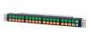
Locations and Functions of Parts Front Panel MKS-R4020 MKS-E1620 LCD buttons Rotary encoders LCD buttons When connected to a system controller, these buttons can be used as source selection buttons, destination selection buttons, or level selection buttons. You can configure the type of - Sony MKS-R4020 | Operating Instructions - Operating InstructionsPDF - Page 6
details about network preferences and connection mode settings, refer to the Installation Manual. You can enter the IP address specified for the unit in a connection or in a redundancy system connection. Several modes are supported for redundancy system connections. Single system connection A single - Sony MKS-R4020 | Operating Instructions - Operating InstructionsPDF - Page 7
Operation In LEO operating mode, all the LCD buttons and rotary encoders are configured and controlled from LEO. For details, refer to the User Manual of Live Element Orchestrator. NS-BUS Operation On the MKS-R4020, all the LCD buttons can be configured as selection buttons or function buttons. You - Sony MKS-R4020 | Operating Instructions - Operating InstructionsPDF - Page 8
Assign function: This function can be assigned to a pinned button only, and a button assigned with the Assign function becomes an ASSGN button. For details about using the ASSGN button, see "Assigning a source/ destination to a selection button (Assign)" (page 9). Source, Destination/Level function: - Sony MKS-R4020 | Operating Instructions - Operating InstructionsPDF - Page 9
Switching crosspoints The source names and destination names for the selection buttons on the front panel are configured using the web menu. Using these buttons, you can select a source and destination for switching a crosspoint. Changing the selection method Set the selection method as described in - Sony MKS-R4020 | Operating Instructions - Operating InstructionsPDF - Page 10
To set a selection button to "No Assign" When a selection button is set to "No Assignment," the source or destination assignment is cleared. Notes • [Enable No Assignment] must be executed on the [Operation Settings] page (page 18) of the web menu. When executed, all source, destination, and - Sony MKS-R4020 | Operating Instructions - Operating InstructionsPDF - Page 11
example, if the control destination is 0015 and the offset value is 2, the crosspoint for destination 0017 is switched. The following usage is supported by a destination offset local salvo. Example 1 To assign a source (audio source 0007, for example) of a level to multiple sources of another level - Sony MKS-R4020 | Operating Instructions - Operating InstructionsPDF - Page 12
2 Assign a salvo to a source in the web menu as described in "Salvo Table Page" (page 16). 3 Assign the source from step 2 to a selection button. When you press the selection button assigned with the salvo function, all the crosspoints configured in the salvo are switched. Take Mode The method for - Sony MKS-R4020 | Operating Instructions - Operating InstructionsPDF - Page 13
Switching sources 1 Set the control destination as a destination for switching a crosspoint as described in "Switching the control destination" (page 8). 2 Set source selection mode as described in "Switching between source selection mode and destination selection mode" (page 8). 3 Press a selection - Sony MKS-R4020 | Operating Instructions - Operating InstructionsPDF - Page 14
web menu. • Up to 10 child devices can be configure for a single parent device. • Linked operation using a mix of MKS-R3210/R1620/ R1630/R4020 is supported. Configuring a child device 1 On the device to set as a child, select the [Child] radio button under [Linkage Settings] in the web menu, and set - Sony MKS-R4020 | Operating Instructions - Operating InstructionsPDF - Page 15
Uploads an updater and updates the system. • User Manual: Displays the Operating Instructions (PDF). • About Remote Control Panel Web Menu: Displays the web menu screen. Reconnect from the browser. Panel Table Page (Not supported on the MKS-E1620.) Use to assign functions to function buttons and - Sony MKS-R4020 | Operating Instructions - Operating InstructionsPDF - Page 16
destination. Monitor Target Number: Enter the monitor target destination number of the destination monitor. 3 Click the [Apply] button. Salvo Table Page (Not supported on the MKS-E1620.) Use to configure a salvo for switching multiple crosspoints at the same time. A salvo can be a snapshot salvo in - Sony MKS-R4020 | Operating Instructions - Operating InstructionsPDF - Page 17
command is issued after the specified time has elapsed when a button is pressed. 6 Click the [Apply] button. Available Src/Dest Page (Not supported on the MKS-E1620.) Use to set the range of sources/destinations available for selection on the unit. Adding a selectable source/destination 1 Click the - Sony MKS-R4020 | Operating Instructions - Operating InstructionsPDF - Page 18
alias names for sources or destinations, respectively. Default Controls Page (Not supported on the MKS-E1620.) Use to set the operation levels and default if any one of the destinations is protected. Select this mode if a problem would occur if any one location does not switch. Button Link: Do not - Sony MKS-R4020 | Operating Instructions - Operating InstructionsPDF - Page 19
the standard colors of the remote control panel (source: green, destination: amber). System: Use the colors specified by the system controller. Sub LCD Color Not supported on the MKS-R4020. Font Size Set the font size. Auto: Set to [L Size] to display up to 8 normal-width characters, or to [M Size - Sony MKS-R4020 | Operating Instructions - Operating InstructionsPDF - Page 20
on the selection button for 2-line display. BASE: Display the base name. 1 to 8: Display the Alias1 to Alias8 name. Retrace Settings Page (Not supported on the MKS-E1620.) Use to configure the function for retracing the crosspoint status display and to display the source names of sources. 1 Enter - Sony MKS-R4020 | Operating Instructions - Operating InstructionsPDF - Page 21
child device selected in the list. Page Group Settings Page (Not supported on the MKS-E1620.) Use to register consecutive pages on the [ connection becomes a single system connection. Manual IP address assignment (Static IP) - Using only LAN1 Set the IP address manually. When a check mark is placed - Sony MKS-R4020 | Operating Instructions - Operating InstructionsPDF - Page 22
result with the server is displayed. If successful, [x] is displayed. If unsuccessful, [-] is displayed. Time setting Use to set the date and time manually. Note • The [Date and Time Settings] configuration is applied when the [Apply] button is clicked. • If the time is not set correctly on - Sony MKS-R4020 | Operating Instructions - Operating InstructionsPDF - Page 23
panel are also reset. CSV Importing and exporting of the following CSV files is supported in [Panel Table], [Salvo Table], [Page Group Settings], [Retrace Settings], and [Source Reentry Lists]. The supported character code set is UTF-8. The delimiter character is a comma (,). If data includes - Sony MKS-R4020 | Operating Instructions - Operating InstructionsPDF - Page 24
, over a long period of use, because of the physical characteristics of the liquid crystal display, such "stuck" pixels may appear spontaneously. These problems are not a malfunction. About the life expectancy of parts The life expectancy of the AC adapter and the electrolytic capacitor is about - Sony MKS-R4020 | Operating Instructions - Operating InstructionsPDF - Page 25
Error/Warning Messages If trouble occurs on the unit, the status lamp lights in red and an error/warning message is displayed on the STATUS button. Warning messages disappear after - Sony MKS-R4020 | Operating Instructions - Operating InstructionsPDF - Page 26
occurred in a Primary connection. Check the network and device connections and settings. If an error persists after taking the appropriate actions above, contact your Sony service or sales representative. 26 - Sony MKS-R4020 | Operating Instructions - Operating InstructionsPDF - Page 27
ANY KIND MADE BY USERS OF THIS UNIT OR MADE BY THIRD PARTIES. • SONY WILL NOT BE LIABLE FOR THE TERMINATION OR DISCONTINUATION OF ANY SERVICES RELATED TO THIS UNIT THAT MAY RESULT DUE TO CIRCUMSTANCES OF ANY KIND. 27
-
 1
1 -
 2
2 -
 3
3 -
 4
4 -
 5
5 -
 6
6 -
 7
7 -
8
-
9
-
10
-
11
-
12
-
13
-
14
-
15
-
16
-
17
-
18
-
19
-
20
-
21
-
22
-
23
-
24
-
25
-
26
-
27
 |
 |

40 LCD Button Remote Control
Panel
MKS-R4020
16 Rotary Encoder Remote Control
Panel
MKS-E1620
Operating Instructions
5-012-212-
12
(1)
© 2019 Sony Corporation