Ryobi RY40540 Operation Manual
Ryobi RY40540 Manual
 |
View all Ryobi RY40540 manuals
Add to My Manuals
Save this manual to your list of manuals |
Ryobi RY40540 manual content summary:
- Ryobi RY40540 | Operation Manual - Page 1
. When properly cared for, it will give you years of rugged, trouble-free performance. WARNING: To reduce the risk of injury, the user must read and understand the operator's manual before using this product. SAVE THIS MANUAL FOR FUTURE REFERENCE Votre accessoire de scie de manche a été conçue - Ryobi RY40540 | Operation Manual - Page 2
Introduction...2 Introduction / Introducción Important Safety Instructions...3-4 Instructions importantes concernant la sécurité / Instrucciones de Troubleshooting...20 Dépannage / Corrección de problemas Warranty...21 Garantie / Garantía Parts Ordering and Service Back Page - Ryobi RY40540 | Operation Manual - Page 3
instructions. Failure to follow all safety instructions when not in use, before servicing , when changing accessories such with this product in the operator's manual. Avoid Dangerous Environments - Do a ladder, rooftop, tree, or unstable support. Stable footing on a solid surface enables better - Ryobi RY40540 | Operation Manual - Page 4
be properly repaired or replaced by an authorized service center unless indicated elsewhere in this manual. SPECIFIC SAFETY RULES Kickback is a down. Follow the sharpening and maintenance instructions for the saw chain. Use only the replacement guide bars and low kickback chains specified for - Ryobi RY40540 | Operation Manual - Page 5
when picking up or holding the appliance. n Remove or disconnect battery before servicing, cleaning or removing material from the gardening appliance. Save these instructions. Refer to them frequently and use them to instruct others who may use this product. If you loan someone this product, loan - Ryobi RY40540 | Operation Manual - Page 6
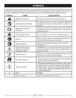
Alert Symbol Indicates a potential personal injury hazard. Read Operator's Manual Wear Eye and Head Protection To reduce the risk of injury, user must read and understand operator's manual before using this product. Always wear eye protection with side shields - Ryobi RY40540 | Operation Manual - Page 7
SYMBOLS The following signal words and meanings are intended to explain the levels of risk associated with this product. SYMBOL SIGNAL MEANING DANGER: Indicates an imminently hazardous situation, which, if not avoided, will result in death or serious injury. WARNING: Indicates a potentially - Ryobi RY40540 | Operation Manual - Page 8
FEATURES PRODUCT SPECIFICATIONS Bar Length 8 in. Cutting Capacity 6 in. Chain Pitch 3/8 in. Chain Type........... Low Profile Skip Tooth Narrow Kerf Weight 6.26 lbs. Compatible With....... Ryobi 24V and 40V Power Head If purchased with 24 V power head: Motor 24 Volts DC If purchased with 40 - Ryobi RY40540 | Operation Manual - Page 9
YOUR POLE SAW See Figure 1. The safe use of this product requires an understanding of the information on the product and in this operator's manual as well as a knowledge of the project you are attempting. Before use of this product, familiarize yourself with all operating features and safety rules - Ryobi RY40540 | Operation Manual - Page 10
fully seated. The plug is larger on one side and will only install one way. WARNING: Failure to secure the attachment and power head as instructed above could result in serious injury or death. n Lower the collar on the power head to the threaded base on the mandatory pole and rotate - Ryobi RY40540 | Operation Manual - Page 11
40 VOLT POWER HEAD ASSEMBLY 24 VOLT POWER HEAD POWER HEAD COLLAR SOCKET PLUG INTERMEDIATE POLE THREADED BASE MANDATORY POLE COLLAR THREADED BASE SOCKET COLLAR CUTTING HEAD POLE POLE SAW ATTACHMENT ATTACHING THE SHOULDER HARNESS See Figure 3. n Connect the latches on the shoulder - Ryobi RY40540 | Operation Manual - Page 12
down and away from you in a safe manner. Disconnect the electrical service to the damaged line or cord before attempting to free the bar and V or Ryobi 40 V battery packs. For complete charging instructions, refer to the Operator's Manuals for your Ryobi battery pack and charger models. ADDING BAR - Ryobi RY40540 | Operation Manual - Page 13
OPERATION TO INSTALL BATTERY PACK See Figure 5. WARNING: Always remove battery pack from your tool when you are assembling parts, making adjustments, cleaning, or when not in use. Removing battery pack will prevent accidental starting that could cause serious personal injury. Insert the battery - Ryobi RY40540 | Operation Manual - Page 14
when the limb falls. n Make a final cut close to trunk. N OTE: For second and final cuts (from top of limb or branch), hold front cutting guide against the limb LOAD SECOND CUT FIRST CUT 1/4 DIAMETER FINAL CUT CUTTING - Ryobi RY40540 | Operation Manual - Page 15
OPERATION being cut. This will help steady the limb and make it easier to cut. Allow chain to cut for you; exert only light downward pressure. If you force the cut, damage to the bar, chain, or motor can result. n Release the trigger as soon as the cut is completed. Failure to follow proper cutting - Ryobi RY40540 | Operation Manual - Page 16
All pole saw service, other than the items listed in these maintenance instructions, should be performed by competent pole saw service personnel. (For chain is correctly tensioned when there is no slack on the underside of the guide bar, the chain is snug, but it can be turned by hand without - Ryobi RY40540 | Operation Manual - Page 17
MAINTENANCE NOTE: New chain tends to stretch; check chain tension frequently and tension as required. NOTICE: Chain tensioned while warm, can be too tight upon cooling. Check the "cold tension" before next use. REPLACING THE BAR AND CHAIN See Figures 14 - 17. CHAIN COVER CHAIN COVER SCREW BAR - Ryobi RY40540 | Operation Manual - Page 18
ability. n If cutter teeth have hit hard objects such as nails and stones, or have been abraded by mud or sand on the wood, have service dealer sharpen chain. CHAIN COVER SCREW LOCK WASHER REMOVE CAP Fig. 17 BAR LUBE RESERVOIR RAKER (DEPTH GAUGE) CLEARANCE Fig. 18 .025 in. Fig. 19 - Ryobi RY40540 | Operation Manual - Page 19
MAINTENANCE HOW TO SHARPEN THE CUTTERS See Figures 20 - 23. Be careful to file all cutters to the specified angles and to the same length, as fast cutting can be obtained only when all cutters are uniform. n Tighten the chain tension enough that the chain does not wobble. Do all of your filing at - Ryobi RY40540 | Operation Manual - Page 20
handling the chain. TROUBLESHOOTING PROBLEM Bar and chain running manual. Inspect guide bar and chain for damage. Battery is not secure. To secure the battery pack, make sure the latch (or latches) snap into place. Battery is not charged. Charge the battery pack according to the instructions - Ryobi RY40540 | Operation Manual - Page 21
work must be performed by an authorized service dealer. This warranty is limited to ninety way contrary to the operating instructions as specified in this operator's manual. This warranty does not and Vacuum Tubes, Vacuum Bag and Straps, Guide Bars, Saw Chains Techtronic Industries North America - Ryobi RY40540 | Operation Manual - Page 22
toutes les instructions de sécurité. Le non respect des instructions de sécurit entretien ou lors du remplacement d'accessoires tels que le guide chaîne. Ne pas travailler hors de portée , une échelle, un toit, un arbre, ou un support instable. Une position stable sur une surface ferme permet de - Ryobi RY40540 | Operation Manual - Page 23
est endommagé devrait être réparé ou remplacé dans un centre de service autorisé, à moins d'une indication contraire dans le présent manuel. RÈ outil. Suivre les instructions d'affûtage et d'entretien fournies par le fabricant de la scie à chaîne. Utiliser exclusivement les guides et chaînes à - Ryobi RY40540 | Operation Manual - Page 24
le faire réparer dans un centre de service autorisé s'il est endommagé. Inspecter ré ou déblocage, lors du remplacement d'accessoires tels que le guide et la chaîne et lorsque l'outil n'est pas en en retirer des matériaux. Conserver ces instructions. Les consulter fréquemment et les utiliser pour - Ryobi RY40540 | Operation Manual - Page 25
. Ne jamais laisser quiconque se tenir à moins de 15 m (50 pi) de l'outil. L'utilisation dans des conditions humides et le non respect des instructions de sécurité peuvent résulter en un choc électrique. Symbole Mains à l'écart Le non-respect de cette mise en garde peut entraîner des blessures - Ryobi RY40540 | Operation Manual - Page 26
SYMBOLES Les termes de mise en garde suivants et leur signification ont pour but d'expliquer le degré de risques associé à l'utilisation de ce produit. SYMBOLE SIGNAL SIGNIFICATION DANGER : AVERTISSEMENT : ATTENTION : AVIS : Indique une situation extrêmement dangereuse qui, si elle n'est pas é - Ryobi RY40540 | Operation Manual - Page 27
203 mm (8 po) Capacité de coupe 152 mm (6 po) Pas de la chaîne 9,5 mm (3/8 po) Type de chaîne Guide d'entaille étroit à denture évidée basse Poids 2,84 kg (6,26 lb) Compatible avec......... bloc-moteur Ryobi de 24 et 40 V Lorsqu'acheté avec bloc-moteur de - Ryobi RY40540 | Operation Manual - Page 28
sécurité. REGARD DE NIVEAU D'HUILE Réservoir de lubrifiant de guide semi-transparent permettant à l'utilisateur de voir à quel moment te de coupe Besoin arbre Intermédiaire arbre Fourreau Clé hex. Lubrifiant pour guide-chaîne et chaîne Bandoulière Manuel d'utilisation Certains modèles peuvent - Ryobi RY40540 | Operation Manual - Page 29
détacher l'un de l'autre. Répéter les étapes décrites précédemment si c'est le cas. AVERTISSEMENT : Ne pas verrouiller l'accessoire et bloc moteur aux instructions ci-dessus peut entraîner des blessures graves et même la mort. RETRAIT DE L'ACCESSOIRE DU BLOC MOTEUR Retirer le bloc-piles. Tourner - Ryobi RY40540 | Operation Manual - Page 30
ARBRE MOTEUR DE 40V ASSEMBLAGE ARBRE MOTEUR DE 24V BLOC MOTEUR COLLIER BOUCHON DOUILLE INTERMÉDIAIRE ARBRE BASE TARAUDÉ BESOIN ARBRE COLLIER BASE TARAUDÉ DOUILLE BOUCHON COLLIER ARBRE DU TÊTE DE COUPE ACCESSOIRE DE SCIE DE MANCHE INSTALLATION DE LA BANDOULIÈRE Voir la figure 3. n - Ryobi RY40540 | Operation Manual - Page 31
ou 40 V de Ryobi. Pour prendre connaissance de l'ensemble des instructions relatives à la charge, consulter les manuels d'utilisation des blocs- Ne pas utiliser d'huile sale, usagée ou autrement contaminée. Cela pourrait endommager le guide ou la chaîne. NOTE : Il est normal que de l'huile suinte de - Ryobi RY40540 | Operation Manual - Page 32
UTILISATION minute. Lorsque la scie est remisée pour une période prolongée (trois mois ou plus), s'assurer que la chaîne et le pignon d'entraînement sont légèrement lubrifiés pour les protéger de la rouille. INSTALLATION DU BLOC-PILES Voir la figura 5. LCUHBARINICANT BOUCHON AVERTISSEMENT : - Ryobi RY40540 | Operation Manual - Page 33
dessous de la branche, près de la branche maîtresse ou du tronc. CHARGE DEUXIÈME COUPE PREMIÈRE COUPE 1/4 DU DIAMÈTRE COUPE FINALE GUIDE DE COUPE Page 14 - Français BOUTON Fig. 6 Fig. 7 Fig. 8 Fig. 9 - Ryobi RY40540 | Operation Manual - Page 34
légèrement vers le bas. Une force excessive pourrait endommager la chaîne, le guide ou le moteur. n Relâcher la gâchette dès que la coupe a ée. Si la bonne procédure de coupe n'est pas respectée, la chaîne et le guide seront pincés ou bloqués dans l'entaille. Dans cette éventualité : n Arrêtez le - Ryobi RY40540 | Operation Manual - Page 35
mouvement s'arrêtent et retirer le bloc-pile. Le non-respect de ces instructions peut entraîner des blessures graves ou des dégâts matériels. ENTRETIEN GÉNÉRAL la vis vers la droite pour tendre la chaîne. Voir Remplacement du guide et de la chaîne plus loin dans ce manuel, pour des informations - Ryobi RY40540 | Operation Manual - Page 36
la chaîne augmente. Les maillons d'entraînement d'une chaîne chaude correctement tendue pendent d'environ 1,27 mm (0,050 po) hors de la rainure du guide comme illustré à la figure 13. NOTE : Les chaînes neuves ont tendance à s'étirer. Il convient donc de vérifier leur tension fréquemment et de la - Ryobi RY40540 | Operation Manual - Page 37
la droite jusqu'à ce que la chaîne soit bien ajustée dans la rainure du guide. n Serrer fermement la vis du carter de la chaîne de montage. NOTE DE LUBRIFICATION DE LA CHAÎNE Voir la figure 18. n Utiliser une lubrifiant pour guide et chaîne Premium. Cette huile, conçue pour les chaînes et huileurs - Ryobi RY40540 | Operation Manual - Page 38
des dents uniformes. n Serrer la chaîne de manière à ce qu'elle n'oscille pas. Tout le limage doit être effectué au point central du guide. Porter des gants protecteurs. n Utiliser une lime ronde de 5/32 po, et un portelime. n Garder la lime de niveau avec la plaque supérieure de - Ryobi RY40540 | Operation Manual - Page 39
n Toujours placer le fourreau sur le guide lors du transport ou du remisage de instructions fournis avec ce modèle. BESOIN D'AIDE? 1-800-860-4050 APPELER LE www.ryobitools.com NOUS APPELER D'ABORD Pour toute question concernant l'utilisation ou l'entretien utiliser ce produit, appeler le service - Ryobi RY40540 | Operation Manual - Page 40
ayant été impliqués dans un accident ou employé de façon contraire aux instructions du manuel d'utilisation. Cette garantie ne couvre ni les dommages aux produits de soufflante, tubes de soufflage et d'aspiration, sacs à débris, guides, chaînes de scie Techtronic Industries North America, Inc., se - Ryobi RY40540 | Operation Manual - Page 41
este producto, que no se haya suministrado con el producto mismo, o que no esté identificado como apropiado para el uso con este producto en el manual del operador. Evite los entornos peligrosos de trabajo - No use el accesorio en lugares húmedos o mojados. No lo use en la lluvia. Vístase - Ryobi RY40540 | Operation Manual - Page 42
esté dañada debe ser reparada apropiadamente o reemplazada en un centro de servicio autorizado, a menos que se indique otra cosa en este manual. REGLAS DE SEGURIDAD ESPECÍFICAS El contragolpe es una reacción peligrosa de la herramienta que puede ocasionar lesiones serias. El contragolpe ocurre - Ryobi RY40540 | Operation Manual - Page 43
REGLAS DE SEGURIDAD ESPECÍFICAS Asegúrese de que el interruptor esté en la posición de de apagado antes de instalar el paquete de baterías. . Dé mantenimiento con cuidado a le producto - Mantenga afilado el filo de corte y límpielo para lograr un desempeño óptimo de la unidad y para reducir el - Ryobi RY40540 | Operation Manual - Page 44
húmedas Guantes EXPLICACIÓN Indica un peligro posible de lesiones personales. Para reducir el riesgo de lesiones, el usuario debe leer y comprender el manual del operador antes de usar este p roducto. Siempre póngase protección ocular con protección lateral con la marca de cumplimiento de la norma - Ryobi RY40540 | Operation Manual - Page 45
SÍMBOLOS Las siguientes palabras de señalización y sus significados tienen el objeto de explicar los niveles de riesgo relacionados con este producto. SÍMBOLO SEÑAL SIGNIFICADO PELIGRO: Indica una situación peligrosa inminente, la cual, si no se evita, causará la muerte o lesiones serias. - Ryobi RY40540 | Operation Manual - Page 46
CARACTERÍSTICAS PRODUCT SPECIFICATIONS Longitud de la barra 203 mm (8 pulg.) Capacidad de corte 152 mm (6 pulg.) Paso de la cadena 9,5 mm (3/8 pulg.) Tipo de cadena corte angosto de dientes de salto de bajo perfil Peso 2,84 kg (6,26 lb.) Compatible con...cabezal motor Ryobi de 24 V y de 40 - Ryobi RY40540 | Operation Manual - Page 47
Vea la figura 1. Para usar este producto con la debida seguridad se debe comprender la información indicada en la producto misma y en este manual, y se debe comprender también el trabajo que intenta realizar. Antes de usar este producto, familiarícese con todas las características de funcionamiento - Ryobi RY40540 | Operation Manual - Page 48
ARMADO ADVERTENCIA: Si falta o está dañada alguna pieza, no utilice este producto sin haber reemplazado la pieza. Usar este producto con partes dañadas o faltantes puede causar lesiones serias al operador. n Repita este procedimiento para conectar la pértiga requiere eje de la cabezal de corte. - Ryobi RY40540 | Operation Manual - Page 49
CABEZAL MOTOR EJE DE 40V ARMADO CABEZAL MOTOR EJE DE 24V CABEZAL MOTOR CASQUILO TOMA-CORRIENTE ENCHUFE INTERMEDIA EJE BASE ROSCADO REQUIERE EJE CASQUILO BASE ROSCADO ENCHUFE TOMA-CORRIENTE CASQUILO EJE DE LA CABEZAL DE CORTE ACCESORIO PARA SIERRA DE PÉRTIGA MONTAJE DE LA CORREA PARA - Ryobi RY40540 | Operation Manual - Page 50
que esté utilizando, este producto admitirá paquetes de baterías Ryobi de 24 V o de 40 V. Para ver las instrucciones de carga completas, consulte los manuales del operador del paquete de baterías Ryobi y los modelos de cargador. ABASTECIMIENTO DE LUBRICANTE PARA LA BARRA Y LA CADENA Vea la figura - Ryobi RY40540 | Operation Manual - Page 51
FUNCIONAMIENTO INSTALACIÓN DEL PAQUETE DE BATERÍAS Vea la figura 5. ADVERTENCIA: Retire siempre el paquete de baterías de la herramienta antes de instalar las piezas, realizar ajustes. limpiarla o cuando no la utilice. Retirar el paquete de baterías evitará que la unidad se accione accidentalmente - Ryobi RY40540 | Operation Manual - Page 52
FUNCIONAMIENTO MANGO DELANTERO AJUSTABLE Vea la figura 6. El ángulo del mango delantero puede ajustarse a 180°. Retire el paquete de baterías. Coloque la motosierra de pértiga en una superficie plana y gire la perilla hacia la izquierda para aflojar el mango. Ajuste el mango si se desea. - Ryobi RY40540 | Operation Manual - Page 53
FUNCIONAMIENTO Esté preparado para equilibrar el peso de la herramienta cuando se caiga la rama. n Efectúe el corte final cerca del tronco. N OTA: Para los cortes segundo y final (por la parte superior de la rama), sostenga la guía de corte del frente contra la rama que se está cortando. Esto - Ryobi RY40540 | Operation Manual - Page 54
serias. Todas las tareas de servicio de la sierra de pértiga, aparte de los puntos indicados en las instrucciones de mantenimiento del manual de instrucciones, deben ser efectuadas por técnicos de servicio de sierra de pértiga competentes. (Por ejemplo, si se utiliza la herramienta inadecuada - Ryobi RY40540 | Operation Manual - Page 55
MANTENIMIENTO n La cadena debe volver a tensarse cada vez que las partes planas de los eslabones de impulsión sobresalen suspendidos de la ranura de la barra, como se muestra en la figura 12. n Durante el funcionamiento normal aumenta la temperatura de la sierra. Si la cadena está bien tensada, - Ryobi RY40540 | Operation Manual - Page 56
MANTENIMIENTO n Vuelva a colocar la cubierta de la cadena y vuelva a instalar la arandela y el tornillo. Apriete sólo con la mano la tornillo. La barra debe quedar libre para moverse para el ajuste de la tensión. n Elimine toda la holgura de la cadena girando el tornillo tensor en el sentido de las - Ryobi RY40540 | Operation Manual - Page 57
MANTENIMIENTO Durante el mantenimiento de la sierra considere lo siguiente: n Un ángulo incorrecto de limadura de la placa lateral puede aumentar el riesgo de un contragolpe violento. n El ajuste de la profundidad determina la profundidad a la que el diente de corte entra en la madera y el tamaño - Ryobi RY40540 | Operation Manual - Page 58
es excesiva. Está vacío el tanque del lubricador de la cadena. Tensión de la cadena. Consulte el apartado Tensado de la cadena, más arriba en este manual. Revise el tanque del lubricador. El motor funciona pero la cadena no avanza. Demasiada tensión en la cadena. Revise el conjunto de la barra gu - Ryobi RY40540 | Operation Manual - Page 59
a un uso indebido, maltrato, negligencia o accidente, o que haya sido utilizado de cualquier forma contraria a las instrucciones de manejo especificadas en el manual del operador del producto. Esta garantía no aplica a ningún daño en el producto que resulte de un mantenimiento indebido ni a ning - Ryobi RY40540 | Operation Manual - Page 60
OPERATOR'S MANUAL MANUEL D'UTILISATION / MANUAL DEL OPERADOR RY40050 POLE SAW ATTACHMENT FOR USE HOW TO OBTAIN CUSTOMER OR TECHNICAL SUPPORT: To obtain Customer or Technical Support please contact us at 1-800-860-4050. • PIÈCES ET SERVICE Avant de faire la demande de service ou l'achat de pièces de
-
 1
1 -
 2
2 -
 3
3 -
 4
4 -
 5
5 -
 6
6 -
 7
7 -
8
-
9
-
10
-
11
-
12
-
13
-
14
-
15
-
16
-
17
-
18
-
19
-
20
-
21
-
22
-
23
-
24
-
25
-
26
-
27
-
28
-
29
-
30
-
31
-
32
-
33
-
34
-
35
-
36
-
37
-
38
-
39
-
40
-
41
-
42
-
43
-
44
-
45
-
46
-
47
-
48
-
49
-
50
-
51
-
52
-
53
-
54
-
55
-
56
-
57
-
58
-
59
-
60
 |
 |

Su accesorio para sierra de pértiga ha sido diseñada y fabricada de
conformidad con las estrictas normas para brindar fiabilidad, facili-
dad de uso y seguridad para el operador. Con el debido cuidado,
le brindará muchos años de sólido y eficiente funcionamiento.
ADVERTENCIA:
Para reducir el riesgo de lesiones,
el usuario debe leer y comprender el manual del operador antes
de usar este producto.
BATTERIES AND CHARGERS SOLD SEPARATELY
PILES ET CHARGEUR VENDUS SÉPARÉMENT
LAS BATERÍAS Y EL CARGADOR SE VENDEN POR SEPARADO
Votre accessoire de scie de manche a été conçue et fabriquée con-
formément à nos strictes normes de fiabilité, simplicité d’emploi et
sécurité d’utilisation. Correctement entretenue, elle vous donnera
des années de fonctionnement robuste et sans problème.
AVERTISSEMENT :
Pour réduire les risques de
blessures, l’utilisateur doit lire et veiller à bien comprendre le
manuel d’utilisation avant d’employer ce produit.
CONSERVER CE MANUEL POUR
FUTURE RÉFÉRENCE
GUARDE ESTE MANUAL PARA
FUTURAS CONSULTAS
SAVE THIS MANUAL FOR FUTURE REFERENCE
Your pole saw attachment has been engineered and manufactured to our high standard for dependability, ease of operation,
and operator safety. When properly cared for, it will give you years of rugged, trouble-free performance.
WARNING:
To reduce the risk of injury, the user must read and understand the operator’s manual before using
this product.
OPERATOR’S MANUAL
MANUEL D’UTILISATION
MANUAL DEL OPERADOR
RY40050
POLE SAW ATTACHMENT
FOR USE WITH RY24001 24 V
OR RY40001B 40 V POWER HEAD
ACCESSOIRE DE SCIE DE MANCHE RY40050
A UTILISER AVEC LE BLOC-MOTEUR RY24001 DE 24 V OU RY40001B DE 40 V
ACCESORIO PARA SIERRA DE PÉRTIGA RY40050
A UTILISER AVEC LE BLOC-MOTEUR RY24001 DE 24 V OU RY40001B DE 40 V
ALL VERSIONS
TOUTES LES VERSIONS/TODAS LAS VERSIONES