Rocketfish RF-TVMLPT02 Quick Setup Guide (English)
Rocketfish RF-TVMLPT02 Manual
 |
UPC - 600603132193
View all Rocketfish RF-TVMLPT02 manuals
Add to My Manuals
Save this manual to your list of manuals |
Rocketfish RF-TVMLPT02 manual content summary:
- Rocketfish RF-TVMLPT02 | Quick Setup Guide (English) - Page 1
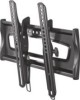
GUIDE RF-TVMLPT02 Thank you for choosing the Rocketfish RF-TVMLPT02. The RF-TVMLPT02 TV mount is designed to support a TV weighing up to 80 lbs. (36.37 kg). Package contents A Wall plate (1) B Left TV bracket (1) C Right TV 2 Install the wall plate Option 1: Installing to a wood stud wall Caution: - Rocketfish RF-TVMLPT02 | Quick Setup Guide (English) - Page 2
Customer Service or call a qualified contractor. Rocketfish is not responsible for damage or injury caused by incorrect installation or use. The weight of your TV must not exceed 80 lbs. (36.37 kg). The wall must be capable of supporting five times the weight of the TV and wall mount combined
-
 1
1 -
 2
2
 |
 |

Tools you will need:
• Stud finder
• Awl
• Pencil
• Level
• Tape measure
Thank you for choosing the
Rocketfish RF-TVMLPT02.
The RF-TVMLPT02 TV mount
is designed to support
a TV weighing up to
80 lbs. (36.37 kg).
• Phillips screw driver
• Hammer (Concrete Only)
• ½ in. socket wrench
• 3/16 in. wood drill bit
• 3/8 in. masonry drill bit (Concrete Only)
• Power drill
QUICK SETUP GUIDE
RF-TVMLPT02
1 Attach the TV brackets
Option 1: Attaching to
a flat mounting
surface
Attach the left and right TV
brackets (B and C) to the
back of the TV using:
The M4/M5 washers (F) and
the M4 x 12 mm screws (D) or
the M5 x 12 mm screws (H).
Or
The M6 washers (M) and
the M6 x 12 mm screws (J) or
the M6 x 20 mm screws (K).
2 Install the wall plate
Option 1: Installing to a wood stud wall
Caution:
Avoid potential injuries or property damage! DO NOT over-tighten the lag bolts.
Note
: Any material covering the wall must
not exceed 5/8 in. (16 mm).
a.
Locate the studs. Verify the center of the stud with an awl or thin nail or use an edge-to-edge stud finder.
b.
Level the wall plate (A) and mark hole locations.
c.
Drill pilot holes as illustrated.
d.
Align the wall plate (A) with the pilot holes, then place the lag bolt washers (Q) over the holes. Insert the
lag bolts (R) through the washers, then tighten the lag bolt with a socket wrench only until they are pulled
firmly against the wall plate.
Package contents
A
Wall plate (1)
B
Left TV bracket (1)
C
Right TV bracket (1)
M4 bag
D
M4 x 12 mm screws (4)
E
M4 x 30 mm screws (4)
F
M4/M5 washers (8)
G
M4/M5 spacers (4)
M5 bag
H
M5 x 12 mm screws (4)
I
M5 x 30 mm screws (4)
M6 bag
J
M6 x 12 mm screws (4)
K
M6 x 20 mm screws (4)
L
M6 x 35 mm screws (4)
M
M6 washers (4)
N
M6 spacers (4)
Hex key bag
O
3⁄16 in. hex key (1)
Lag bolt bag
P
Concrete anchors (3)
Q
Lag bolt washers (3)
R
5⁄16 in. x 23⁄4 in. lag bolts (3)
A
B
C
M4 x 12mm
M5 x 12mm
M6 x 12mm
M4 x 30mm
M5 x 30mm
M6 x 20mm
in. x 2
in.
M6 x 35mm
M4 bag
Hex key bag
M5 bag
M6 bag
Lag bolt bag
D
H
O
G
R
P
Q
I
J
E
K
L
F
M
N
Option 2: Attaching to a curved or
irregular mounting surface
Attach the left and right TV brackets (B and C)
to the back of the TV using:
The M4/M5 spacers (G), M4/M5 washers (F),
and the M4 x 30 mm screws (E) or M5 x 30 mm
screws (I).
Or
The M6 spacers (N), M6 washers (M), and
the M6 x 35 mm screws (L).
Note:
Use the M4 washers (F) between
the spacers and the bracket with the M4
or M5 screws only.
A
Q
R
< 16 mm
(
5
/8
in.)
J
K
B
C
F
M
H
D
B
C
I
L
N
B
C
E
G
F
M
F
B
C
a.
b.
c.
d.
or
or
or
or
or
75mm
3 in.
M4/M5
M4/M5
M6
M6