Rane MT4 VR2 Remote Data Sheet / Manual
Rane MT4 Manual
 |
View all Rane MT4 manuals
Add to My Manuals
Save this manual to your list of manuals |
Rane MT4 manual content summary:
- Rane MT4 | VR2 Remote Data Sheet / Manual - Page 1
DATA SHEET / MANUAL VR2 VOLUME REMOTE Description The VR2 mounts in a standard US electrical , irreparable damage to the VR2, requiring replacement of the remote. Such damage is not covered by Rane's warranty; checking the wiring is easier than a second trip to the job site with another remote - Rane MT4 | VR2 Remote Data Sheet / Manual - Page 2
as the GND return) for longer runs (200 to 1000 ft.). The type of wire required is influenced by your installation and local electrical codes. Rane Corporation does not provide or source cable. Please contact your local retail or wholesale outlet, not the factory. The following is a short list of
-
 1
1 -
 2
2
 |
 |
DATA SHEET / MANUAL
VR2
VOLUME REMOTE
Description
°e VR2 mounts in a standard US electrical box and can be
covered with a Decora plate. It contains a linear taper potentiom-
eter with a single Euroblock screw terminal for each of the pot’s
three conductors, the Vr terminal, the Vc wiper terminal, and the
ground terminal.
Connection
Turn the power to the unit off until all connections are made.
Con-
nect the VR2's
control voltage Vc (wiper) connection(s) first.
°en connect the voltage reference - “Vr” on the VR2 (“REF”
terminal on a RPM unit). Connect the GND (ground) terminal
last. Double and triple check your wiring before applying power
to the MA 4 or RPM since improper wiring can and will cause
permanent, irreparable damage to the VR2, requiring replace-
ment of the remote.
Such damage is not covered by Rane's war-
ranty
; checking the wiring is easier than a second trip to the job
site with another remote.
Euroblocks
Be sure to note the wire color of each input in order to facilitate
correct wiring to the controlled unit. If the ground or shield wire
is left shorter, it acts as a strain relief for the other wires. Con-
nect each wire to the 3-pin connector by fully inserting it in the
correct socket and tightening the screw. Make sure wires are free
of nicks and that the cable jacket is stripped back sufficiently
to allow it to lie in the electrical box with the remote assembly
inserted.
Voltages
Turn the power to the unit
off
until all connections are made. It
is important to ensure that the Remote Ports are not subjected
to sustained voltages outside the range of 0 to 5 volts DC or
high levels of static. Inputs are protected, however, caution is the
better part of... you know. It is a good idea to install the wiring,
connect it to the Remote and then make the final connections at
the Remote Port.
Do
not
short the Vref pin to ground. °is pin is current
limited, however, excess heat is generated in the 5 volt supply if a
short occurs.
Never subject the Vr pin to voltages above 5 volts.
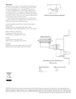
Remote Mounting
°e VR2 remote assembly mounts in a standard U.S. electrical
box with a minimum depth of 2.25" (5.5 cm). Use the flat head
#6 screws supplied with the kit to mount the remote assembly
and silk-screened front panel to the electrical box.
Install the knob so that the line on the knob is properly
aligned with the silk-screening on the front panel of the remote.
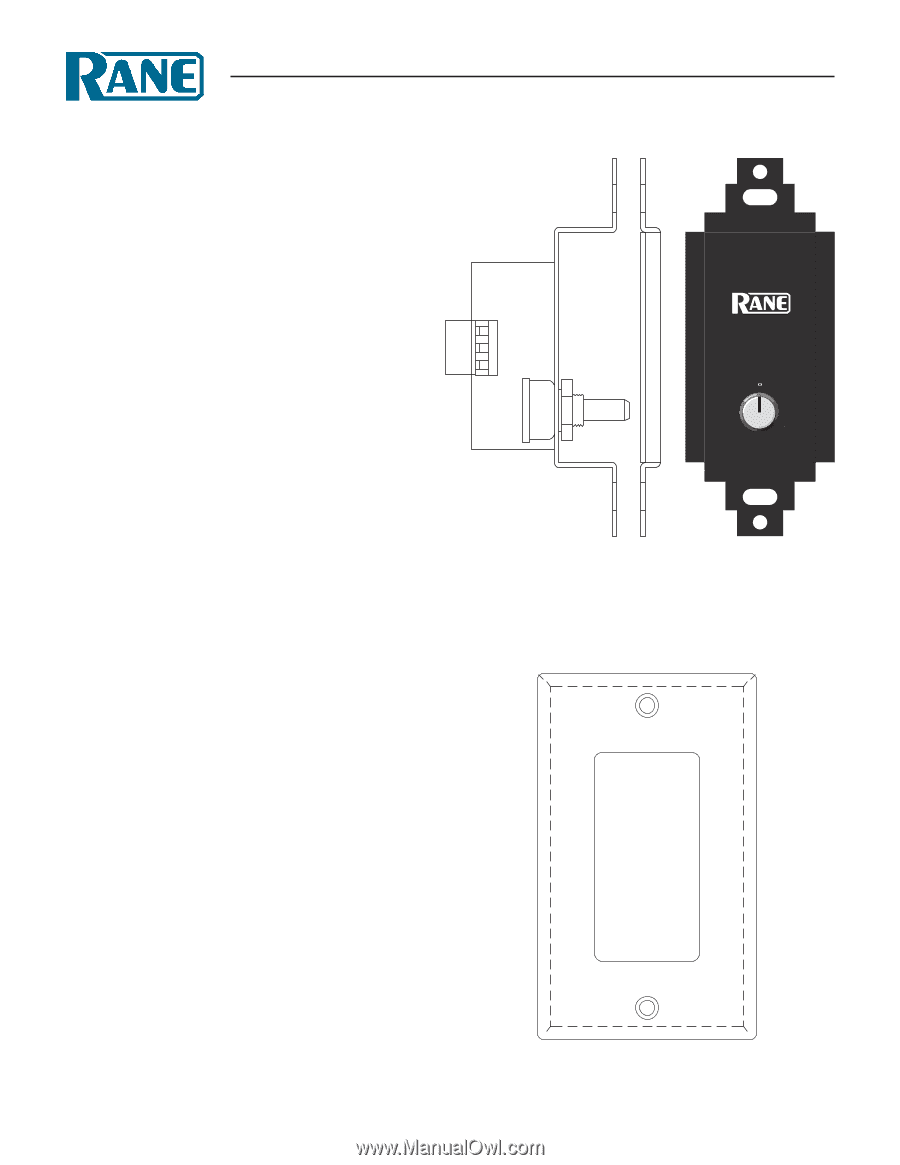
Install any Decora plate of your choice. For a secured installa-
tion, you may wish to leave the knobs off and use a blank Decora
plate to cover the remote after adjustment.
Vc
GND
Vr
4
0
2
6
8
10
LEVEL
Decora plate cover, not supplied.