MSI MEG X570 UNIFY User Manual
MSI MEG X570 UNIFY Manual
 |
View all MSI MEG X570 UNIFY manuals
Add to My Manuals
Save this manual to your list of manuals |
MSI MEG X570 UNIFY manual content summary:
- MSI MEG X570 UNIFY | User Manual - Page 1
Start Thank you for purchasing the MSI® MEG X570 UNIFY motherboard. This Quick Start section provides demonstration the URL by scanning the QR code. Preparing Tools and Components AMD® AM4 CPU CPU Fan DDR4 Memory Power Supply Unit Chassis Graphics Card Thermal Paste SATA Hard Disk Drive SATA - MSI MEG X570 UNIFY | User Manual - Page 2
discharge (ESD). Please adhere to the following instructions to ensure successful computer assembly. y Ensure that power supply and unplug the power cord from the power outlet before installing or removing any computer component. y Keep this user guide for future reference. y Keep this motherboard - MSI MEG X570 UNIFY | User Manual - Page 3
Installing a Processor https://youtu.be/Xv89nhFk1vc 3 2 1 5 4 8 6 9 7 Quick Start 3 - MSI MEG X570 UNIFY | User Manual - Page 4
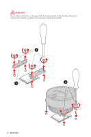
Important If you are installing the screw-type CPU heatsink, please follow the figure below to remove the retention module first and then install the heatsink. 1 2 3 4 Quick Start - MSI MEG X570 UNIFY | User Manual - Page 5
Installing DDR4 memory http://youtu.be/T03aDrJPyQs DIMMA2 DIMMA2 DIMMB2 DIMMA1 DIMMA2 DIMMB1 DIMMB2 Quick Start 5 - MSI MEG X570 UNIFY | User Manual - Page 6
POPWOEWRELREHLDD-EDDL+ED RESET SW POWER SW Power LED Power Switch - -+ -- ++ JFP1 2 1 + 10 9 Reserved HDD LED Reset Switch 1 HDD LED + 2 3 HDD LED - 4 5 Reset Switch 6 7 Reset Switch 8 9 Reserved 10 Power LED + Power LED Power Switch Power Switch No Pin HDD LED - MSI MEG X570 UNIFY | User Manual - Page 7
Installing the Motherboard 1 2 BAT1 Quick Start 7 - MSI MEG X570 UNIFY | User Manual - Page 8
Connecting the Power Connectors http://youtu.be/gkDYyR_83I4 ATX_PWR1 CPU_PWR1 8 Quick Start CPU_PWR2 - MSI MEG X570 UNIFY | User Manual - Page 9
Installing SATA Drives http://youtu.be/RZsMpqxythc 2 1 3 5 4 Quick Start 9 - MSI MEG X570 UNIFY | User Manual - Page 10
Installing a Graphics Card http://youtu.be/mG0GZpr9w_A 1 3 2 5 10 Quick Start 4 6 - MSI MEG X570 UNIFY | User Manual - Page 11
Connecting Peripheral Devices Quick Start 11 - MSI MEG X570 UNIFY | User Manual - Page 12
Power On 1 2 3 4 12 Quick Start - MSI MEG X570 UNIFY | User Manual - Page 13
Preparing Tools and Components 1 Safety Information 2 Installing a Processor 3 Installing DDR4 memory 5 Connecting the Front Panel Header 6 Installing the Motherboard 7 Connecting the Power Connectors 8 Installing SATA Drives 9 Installing a Graphics Card 10 Connecting Peripheral Devices 11 - MSI MEG X570 UNIFY | User Manual - Page 14
Connector 47 Onboard LEDs ...48 EZ Debug LED...48 JPWRLED1: LED power input 48 Debug Code LED 48 Hexadecimal Character Table 49 Boot Phases...49 ACPI States Codes 53 Installing OS, Drivers & Utilities 54 Installing Windows® 10 54 Installing Drivers 54 Installing Utilities 54 BIOS Setup ... - MSI MEG X570 UNIFY | User Manual - Page 15
Microphone Tab ...78 Sound Tracker Tab 79 Settings Tab ...79 AMD RAID Configuration 80 Enabling RAIDXpert2 Configuration Utility 80 Initializing Disks 81 Creating Arrays...82 Deleting Arrays ...83 Installing RAID Driver 84 Troubleshooting 85 Contents 15 - MSI MEG X570 UNIFY | User Manual - Page 16
AMD Ryzen™ with Radeon™ Graphics Desktop Processors for Socket AM4 AMD® X570 Chipset y 4x DDR4 memory slots, support up to 128GB* ƒ 3rd Gen AMD Ryzen™ Processors support y Supports non-ECC UDIMM memory y Supports ECC UDIMM memory (non-ECC mode) y Supports un-buffered memory * Please refer www.msi.com - MSI MEG X570 UNIFY | User Manual - Page 17
ac/ax, MU-MINO Rx, 2.4GHz5GHz (160MHz) up to 2.4Gbps ƒ Supports Bluetooth® 5 ƒ The Wireless module is pre-install in the M2_4 (Key-E) slot Realtek® ALC1220 Codec y 7.1-Channel High Definition Audio y Supports Optical S/PDIF output AMD® X570 Chipset y 4x SATA 6Gb/s ports y 2x M.2 slots (M2_2/ M2_3 - MSI MEG X570 UNIFY | User Manual - Page 18
Continued from previous page USB I/O Controller Hardware Monitor Form Factor AMD® X570 Chipset ƒ 3x USB 3.2 Gen2 (SuperSpeed USB 10Gbps) ports (2 Type-A ports on the back panel, 1 Type-C internal connector) ƒ 4x USB 3.2 Gen1 (SuperSpeed USB) ports through the - MSI MEG X570 UNIFY | User Manual - Page 19
previous page Internal Connectors y 1x 24-pin ATX main power connector y 2x 8-pin ATX 12V power connectors y 4x SATA 6Gb/s connectors y 2x USB 2.0 connectors (support additional 4 USB 2.0 ports) y 2x USB 3.2 Gen 1 connectors (support additional 4 USB 3.2 Gen 1 ports) y 1x USB 3.2 Gen 2 Type-C Port - MSI MEG X570 UNIFY | User Manual - Page 20
1x Clear CMOS Button y 1x Flash BIOS Button y 1x WiFi/ Bluetooth module y 1x PS/2 keyboard/ mouse combo port y 2x USB y Multi-language y Drivers y DRAGON CENTER y Nahimic Audio y CPU-Z MSI GAMING y MSI App Player (BlueStacks) http://download.msi.com/manual/ mb/DRAGONCENTER2.pdf for more details. - MSI MEG X570 UNIFY | User Manual - Page 21
Special Features Continued from previous page y Audio ƒ Audio Boost HD ƒ Nahimic 3 ƒ Voice Boost y Network ƒ LAN Manager ƒ 2.5G LAN ƒ Intel WiFi AX y Storage ƒ Lightning Gen 4 M.2 ƒ Triple M.2 y Cooling ƒ Zero Frozr Technology ƒ Frozr Heatsink Design ƒ Propeller Blade technology ƒ M.2 Shield Frozr - MSI MEG X570 UNIFY | User Manual - Page 22
ƒ Lightning Gen 4 PCI-E Slot ƒ Multi GPU-SLI Technology ƒ Multi GPU-CrossFire Technology ƒ DDR4 Boost ƒ Core Boost ƒ GAME Boost ƒ OC Engine (Clock gen) ƒ USB with type A+C ƒ AMD Turbo USB 3.2 Gen 2 ƒ Front USB Type-C ƒ Dual CPU Power y USER Experience ƒ Dragon Center ƒ Gaming Hotkey ƒ Speed - MSI MEG X570 UNIFY | User Manual - Page 23
Package contents Please check the contents of your motherboard package. It should contain: Motherboard MEG X570 UNIFY SATA 6Gb/s Cables 4 Cable 1 to Product Registration Card 1 Application DVD Driver DVD 1 User Manual 1 Documentation Quick Installation Guide 1 Important If any of the - MSI MEG X570 UNIFY | User Manual - Page 24
Block Diagram Switch PCI Express Bus 2x M.2 4x SATA 6Gb/s 6x USB 2.0 4x USB 3.2 Gen1 3x USB 3.2 Gen2 2 Channel DDR4 Memory Processor 1x M.2 2x USB 3.2 Gen1 PCIE PCH 2x USB 3.2 Gen2 Realtek Front Audio Jacks ALC1220 Rear Audio Jacks NUVOTON 6797 P/S2 Mouse/ Keyboard 1x Intel Wi-Fi 6 AX200 1x - MSI MEG X570 UNIFY | User Manual - Page 25
Type-A USB 3.2 Gen 2 Flash BIOS Port Type-A* *USB 3.2 Gen2 (3rd Gen AMD Ryzen™) or USB 3.2 Gen1 (2nd Gen AMD Ryzen™/ Ryzen™ with Radeon™ Vega Graphics and 2nd Gen AMD Ryzen™ with Radeon™ Graphics) yyClear CMOS button - Power off your computer. Press and hold the Clear CMOS button for about 5-10 - MSI MEG X570 UNIFY | User Manual - Page 26
Realtek Audio Console After Realtek Audio Console is installed. You can use it to change sound settings to get better sound experience. Application Enhancement Device Selection Main Volume Connector Settings Jack Status yyDevice Selection - allows you to select a audio output source to change the - MSI MEG X570 UNIFY | User Manual - Page 27
Audio jacks to headphone and microphone diagram Audio jacks to stereo speakers diagram AUDIO INPUT Audio jacks to 7.1-channel speakers diagram AUDIO INPUT Rear Front Side Center/ Subwoofer Rear I/O Panel 27 - MSI MEG X570 UNIFY | User Manual - Page 28
Installing Antennas 1. Combine the antenna with the base. 2. Screw two antenna cables tight to the WiFi antenna connectors as shown. 2 1 3. Place the antenna as high as possible. 28 Rear I/O Panel - MSI MEG X570 UNIFY | User Manual - Page 29
Overview of Components PCI_E1 PCI_E2 JBAT1 JCI1 PCI_E3 M2_3 PCI_E4 JTPM1 PCI_E5 JRAINBOW2 CPU_PWR2 CPU_PWR1 Processor Socket CPU_FAN1 PUMP_FAN1 JRGB1 JCORSAIR1 SYS_FAN4 DIMMB2 SYS_FAN2 DIMMB1 DIMMA2 DIMMA1 SYS_FAN5 ATX_PWR1 BAT1 JAUD1 SYS_FAN1 SYS_FAN3 JPWRLED1 JUSB4 JUSB5 RESET1 POWER1 - MSI MEG X570 UNIFY | User Manual - Page 30
Intrusion Connector 43 CORSAIR Connector 47 Front Panel Connectors 38 LED power input 48 Addressable RGB LED connectors 46 RGB LED connector 45 TPM (Key M) 36 PCIe Expansion Slots 33 Power Button, Reset Button 44 AM4 socket 31 SATA 6Gb/s Connectors 38 30 Overview of Components - MSI MEG X570 UNIFY | User Manual - Page 31
processor for motherboard placement. The yellow triangle is the Pin 1 indicator. Important yyWhen changing the processor, the system configuration could be cleared and reset BIOS to default values, due to the AM4 processor's architecture. yyAlways unplug the power cord from the power outlet before - MSI MEG X570 UNIFY | User Manual - Page 32
or overclocking. yyThe stability and compatibility of installed memory module depend on installed CPU and devices when overclocking. yyDue to AM4 processor/ memory controller official specification limitation, the frequency of memory modules may operate lower than the marked value under the - MSI MEG X570 UNIFY | User Manual - Page 33
MSI Gaming Series Graphics Card Bolster to support its weight to prevent deformation of the slot. yyFor a single PCIe x16 expansion card installation with optimum performance, using the PCI_E1 slot is recommended. yyWhen adding or removing expansion cards, always turn off the power supply Gen AMD - MSI MEG X570 UNIFY | User Manual - Page 34
For 2nd Gen AMD Ryzen™ Slot Single 2-Way PCI_E1 (CPU) @3.0 x16 @3.0 x8 PCI_E2 (PCH) 3.0 x1 - 3.0 x1 - PCI_E3 - @3.0 x8 - 3.0 x1 @3.0 x4 For Ryzen™ with Radeon™ Vega Graphics and 2nd Gen AMD Ryzen™ with Radeon™ Graphics Slot Single PCI_E1 (CPU) @3.0 x8 PCI_E2 (PCH) 3.0 x1 - - MSI MEG X570 UNIFY | User Manual - Page 35
graphics cards For power supply recommendations for SLI configurations, please refer to the user guide of your graphics card to make sure you meet all the system requirements. To install SLI graphics cards: 1. Turn off your computer and disconnect the power cord, install two graphics cards into the - MSI MEG X570 UNIFY | User Manual - Page 36
M) The following table describes the relationship between the M.2 slots and the PCIe bandwidth of the processors. M2_1 M2_2 M2_3 Slots 3rd Gen AMD 2nd Gen AMD Ryzen™ Ryzen™ M2_1 (CPU) M2_2 (PCH) M2_3 (PCH) PCIe 4.0 x4 PCIe 4.0 x4 PCIe 4.0 x4 PCIe 3.0 x4 PCIe 3.0 x4 PCIe 3.0 x4 Ryzen™ with - MSI MEG X570 UNIFY | User Manual - Page 37
4. Insert your M.2 SSDs into the M.2 slots at a 30-degree angle. 5. If the M.2 SSD is shorter than the M.2 SHIELD FROZR heatsink, please secure the M.2 SSD in place with M.2 screw. If the length of M.2 SSD equals the M.2 SHIELD FROZR heatsink, please skip this step. M.2 screw 5 M.2 standoff - MSI MEG X570 UNIFY | User Manual - Page 38
it is recommended that the flat connector be connected to the motherboard for space saving purposes. JFP1, JFP2: Front Panel Connectors These to the switches and LEDs on the front panel. JFP1 1 3 5 7 9 Power Switch Power LED HDD LED + HDD LED Reset Switch Reset Switch Reserved ++ -- -+ - 10 - MSI MEG X570 UNIFY | User Manual - Page 39
PS-ON# Ground Ground Ground Res +5V +5V +5V Ground Important Make sure that all the power cables are securely connected to a proper ATX power supply to ensure stable operation of the motherboard. JAUD1: Front Audio Connector This connector allows you to connect audio jacks on the front panel - MSI MEG X570 UNIFY | User Manual - Page 40
These connectors allow you to connect USB 3.2 Gen1 ports on the front panel. 10 11 1 10 JUSB3 1 20 20 11 JUSB2 1 Power 11 2 USB3_RX_DN 12 3 USB3_RX_DP 13 4 Ground 14 5 USB3_TX_C_DN 15 6 USB3_TX_C_DP 16 7 Ground 17 8 USB2.0- 18 9 USB2.0+ 19 10 NC 20 USB2 - MSI MEG X570 UNIFY | User Manual - Page 41
recharge your iPad,iPhone and iPod through USB ports, please install MSI® DRAGON CENTER utility. JTPM1: TPM Module Connector This connector is the TPM security platform manual for more details and usages. 2 14 1 13 1 LPC Clock 2 3V Standby power 3 LPC Reset 4 3.3V Power 5 LPC address & - MSI MEG X570 UNIFY | User Manual - Page 42
12V output and adjust fan speed with speed control signal. DC Mode fan connectors control fan speed by changing voltage. You can follow the instruction below to adjust the fan connector to PWM or DC Mode. Default PWM Mode fan connectors 1 CPU_FAN1 / PUMP_FAN1 Default DC Mode fan connectors - MSI MEG X570 UNIFY | User Manual - Page 43
JCI1: Chassis Intrusion Connector This connector allows you to connect the chassis intrusion switch cable. Normal (default) Trigger the chassis intrusion event Using chassis intrusion detector 1. Connect the JCI1 connector to the chassis intrusion switch/ sensor on the chassis. 2. Close the - MSI MEG X570 UNIFY | User Manual - Page 44
JBAT1: Clear CMOS (Reset BIOS) Jumper There is CMOS memory onboard that is external powered from a battery located on the motherboard to save system configuration data. If you want to clear the system configuration, set the jumpers to clear the CMOS memory. Keep Data (default) Clear - MSI MEG X570 UNIFY | User Manual - Page 45
yyThe JRGB connector supports up to 2 meters continuous 5050 RGB LED strips (12V/G/R/B) with the maximum power rating of 3A (12V). yyAlways turn off the power supply and unplug the power cord from the power outlet before installing or removing the RGB LED strip. yyPlease use MSI's software to - MSI MEG X570 UNIFY | User Manual - Page 46
3A (5V). In the case of 20% brightness, the connector supports up to 200 LEDs. yyAlways turn off the power supply and unplug the power cord from the power outlet before installing or removing the RGB LED strip. yyPlease use MSI's software to control the extended LED strip. 46 Overview of Components - MSI MEG X570 UNIFY | User Manual - Page 47
fans with MSI's software. 1 JCORSAIR1 1 +5V 2 3 Ground Data CORSAIR RGB Fan Connection CORSAIR RGB LED fan SATA power SYS_FAN CORSAIR Fans or RGB LED Lighting PRO strips supported may differ between models. Please refer to the motherboard specification. yyCORSAIR RGB LED Fan and CORSAIR - MSI MEG X570 UNIFY | User Manual - Page 48
LEDs indicate the debug status of the motherboard. CPU - indicates CPU is not detected or fail. DRAM - indicates DRAM is not detected or fail. VGA - indicates GPU is not detected or fail. BOOT - indicates the booting device is not detected or fail. JPWRLED1: LED power input This connector is used by - MSI MEG X570 UNIFY | User Manual - Page 49
level initialization Pre-EFI Initialization (PEI) - memory initialization Driver Execution Environment (DXE) - main hardware initialization Boot Device , Network, Shell, ...) Debug Code LED Table SEC Progress Codes 01 Power on. Reset type detection (soft/hard) 02 AP initialization before microcode - MSI MEG X570 UNIFY | User Manual - Page 50
Codes 60 DXE Core is started 61 NVRAM initialization 62 Installation of the PCH Runtime Services 63 CPU DXE initialization is started 64 - 67 CPU DXE initialization (CPU module specific (BDS) phase is started 91 Driver connecting is started 92 PCI Bus initialization is started 50 Onboard LEDs - MSI MEG X570 UNIFY | User Manual - Page 51
Enable A8 Setup Verifying Password A9 Start of Setup AB Setup Input Wait AD Ready To Boot event AE Legacy Boot event AF Exit Boot Services event B0 Runtime Set Virtual Address MAP Begin B1 Runtime Set Virtual Address MAP End B2 Legacy Option ROM Initialization B3 System Reset B4 USB - MSI MEG X570 UNIFY | User Manual - Page 52
D3 Some of the Architectural Protocols are not available D4 PCI resource allocation error. Out of Resources D5 No Space for Legacy Option ROM D6 No Console Output Devices are found D7 No Console Input Devices are found D8 Invalid password D9 Error loading Boot Option (LoadImage returned error) DA - MSI MEG X570 UNIFY | User Manual - Page 53
ACPI States Codes The following codes appear after booting and the operating system into ACPI modes. 01 System is entering S1 sleep state 02 System is entering S2 sleep state 03 System is entering S3 sleep state 04 System is entering S4 sleep state 05 System is entering S5 sleep state 10 System is - MSI MEG X570 UNIFY | User Manual - Page 54
POST (Power-On Self Test) to get into Boot Menu. 5. Select the Windows® 10 installation disc/USB from the Boot Menu. 6. Press any key when screen shows Press any key to boot from CD or DVD... message. 7. Follow the instructions on the screen to install Windows® 10. Installing Drivers 1. Start - MSI MEG X570 UNIFY | User Manual - Page 55
BIOS Setup The default settings offer the optimal performance for system stability in normal conditions. You should always keep the default settings to avoid possible system damage or failure booting unless you are familiar with BIOS. Important yyBIOS items are continuously update for better system - MSI MEG X570 UNIFY | User Manual - Page 56
problems. There are several ways to reset BIOS: yyGo to BIOS and press F6 to load optimized defaults. yyShort the Clear CMOS jumper on the motherboard BIOS file that matches your motherboard model from MSI website. And then save the with MSI DRAGON CENTER Before updating: Make sure the LAN driver is - MSI MEG X570 UNIFY | User Manual - Page 57
that matches your motherboard model from MSI® website and rename the BIOS file to MSI.ROM. And then, save the MSI.ROM file to the root of USB flash drive. Important Only the FAT32 format USB flash drive supports updating BIOS by Flash BIOS Button. 1. Connect power supply to CPU_PWR1 and ATX_PWR1 - MSI MEG X570 UNIFY | User Manual - Page 58
This switch will only be available if the installed processor and memory modules support A-XMP function. yySetup Mode switch - press this tab or the , MB/ CPU type, memory size, CPU/ DDR voltage, BIOS version and build date. yyBoot device priority bar - you can move the device icons to change - MSI MEG X570 UNIFY | User Manual - Page 59
the way to update BIOS with a USB flash drive. yyHardware Monitor - click on this button to display the Hardware Monitor menu that allows you to manually control the fan speed by percentage. yyFavorites - press the F3 key to enter Favorites menu. It allows you to create personal BIOS menu where you - MSI MEG X570 UNIFY | User Manual - Page 60
. ƒƒHARDWARE MONITOR - allows you to set the speeds of fans and monitor voltages of system. ƒƒBOARD EXPLORER - provides the information of installed devices on this motherboard. yyMenu display - provides BIOS setting items and information to be configured. 60 BIOS Setup - MSI MEG X570 UNIFY | User Manual - Page 61
. Important If the connected SATA device is not displayed, turn off computer and re-check SATA cable and power cable connections of the device and motherboard. ffSystem Information Shows detailed system information, including CPU type, BIOS version, and Memory (read only). ffDMI Information Shows - MSI MEG X570 UNIFY | User Manual - Page 62
system supports MSI M.2 Xpander-Z / Other M.2 PCIe storage card. The options in this item will vary with the installed processor. ffACPI Settings Sets ACPI parameters of onboard power LED behaviors. Press Enter to enter the submenu. ffPower LED [Blinking] Sets shining behaviors of the onboard Power - MSI MEG X570 UNIFY | User Manual - Page 63
to enter the sub-menu. ffErP Ready [Disabled] Enables or disables the system power consumption according to ErP regulation. [Enabled] Optimize the system power consumption according to ErP regulation. It will not support S4 & S5 wake up by USB, PCI and PCIe devices. [Disabled] Disables this - MSI MEG X570 UNIFY | User Manual - Page 64
to enter the submenu. ffBIOS UEFI/CSM Mode [CSM] Select CSM (Compatibility Support Module) or UEFI mode to meet the system requirement. [CSM] For the non-UEFI driver add-on devices or non-UEFI mode OS. [UEFI] For the UEFI driver add-on devices and UEFI mode OS. ffSecure Boot Sets the Windows - MSI MEG X570 UNIFY | User Manual - Page 65
up function of installed PCI-E expansion cards, integrated LAN controllers or USB devices which are supported by third party integrated chips. [Enabled] Enables the system to be awakened from the power saving modes when activity or input signal of PCIe device is detected. [Disabled] Disables this - MSI MEG X570 UNIFY | User Manual - Page 66
and will be configured automatically by BIOS when BIOS UEFI/CSM Mode sets to UEFI. [UEFI] [LEGACY+UEFI] Enables UEFI BIOS boot mode support only. Enables both Legacy BIOS boot mode and UEFI BIOS boot mode. ffFIXED BOOT ORDER Priorities Sets device priority for system boot. ffBoot Option - MSI MEG X570 UNIFY | User Manual - Page 67
Enables or disables the TPM function to build the endorsement key for accessing the system. ffAMD fTPM switch [AMD CPU fTPM] Selects TPM device. This item will appear when Security Device Support is enabled. [AMD CPU fTPM] Select it for AMD Firmware TPM. [AMD CPU fTPM Disabled] Select it for - MSI MEG X570 UNIFY | User Manual - Page 68
Save & Exit ffDiscard Changes and Exit Exit BIOS setup without saving any change. ffSave Changes and Reboot Save all changes and reboot the system. ffSave Changes Save current changes. ffDiscard Changes Discard all changes and restore to the previous values. ffRestore Defaults Restore or load all - MSI MEG X570 UNIFY | User Manual - Page 69
your PC manually is only supports this function. ffAdvanced CPU Configuration Press Enter to enter the sub-menu. User can set the parameters about CPU power/ be available when the installed processor, memory modules and motherboard support this function. ffDRAM Frequency [Auto] Sets the DRAM - MSI MEG X570 UNIFY | User Manual - Page 70
the digital powers related to CPU PWM. ffCPU Loadline Calibration Control [Auto] The CPU voltage will decrease proportionally according to CPU loading. Higher load-line calibration could get higher voltage and good overclocking performance, but increase the temperature of the CPU and VRM. If set - MSI MEG X570 UNIFY | User Manual - Page 71
automatically or you can set it manually. ffDRAM Voltages control [Auto] These AMD Simultaneous Multi-Threading. This item appears when the installed CPU supports instruction to save the decoding time when the instruction is repeated. And it may increase the CPU performance and reduce the power - MSI MEG X570 UNIFY | User Manual - Page 72
) problem. power consumption. ffSVM Mode [Enabled] Enables/ disables the AMD SVM (Secure Virtual Machine) Mode. ffBIOS PSP Support [Enabled] (optional) Enables/ disables the BIOS PSP support. It manages PSP sub-items including all C2P/P2C mailbox, Secure S3, fTPM support. ffPower Supply - MSI MEG X570 UNIFY | User Manual - Page 73
M-FLASH M-FLASH provides the way to update BIOS with a USB flash drive. Please download the latest BIOS file that matches your motherboard model from MSI website, save the BIOS file into your USB flash drive. And then follow the steps below to update BIOS. 1. Insert the USB flash drive that - MSI MEG X570 UNIFY | User Manual - Page 74
OC PROFILE ffOverclocking Profile 1/ 2/ 3/ 4/ 5/ 6 Overclocking Profile 1/ 2/ 3/ 4/ 5/ 6 management. Press Enter to enter the sub-menu. ffSet Name for Overclocking Profile 1/ 2/ 3/ 4/ 5/ 6 Name the current overclocking profile. ffSave Overclocking Profile 1/ 2/ 3/ 4/ 5/ 6 Save the current - MSI MEG X570 UNIFY | User Manual - Page 75
HARDWARE MONITOR Temperature & Speed Fan Manage Setting Buttons Temperature/ Voltage display ffTemperature & Speed Shows the current CPU temperature, system temperature and fans' speeds. ffFan Manage ƒƒPWM - allows you to select the PWM mode for fan operation. ƒƒDC - allows you to select the DC - MSI MEG X570 UNIFY | User Manual - Page 76
A-XMP Operation System Requirements yySupported AMD® Ryzen™ series processor yyMemory module supports XMP How to enable A-XMP Power on and press Delete key to enter BIOS Setup menu. Here are two profile. yyThe A-XMP button and item are only available when the system is supported. 76 BIOS Setup - MSI MEG X570 UNIFY | User Manual - Page 77
effects and Sound Tracker. Installation and Update Nahimic 3 is included in the audio driver. If you need to install it or update it, please use the Driver Disc with your motherboard or download the driver from MSI's official website. Audio Tab From this tab, you can access all of Nahimic - MSI MEG X570 UNIFY | User Manual - Page 78
-12 to +12 dB. y Reset Button - restores the current profile to its default values. y Try Button - launches an audio sample that allows to test audio settings. Microphone Tab From this tab, you can access all of Nahimic 3's microphone effects and settings. Device display & Volume On/Off Button - MSI MEG X570 UNIFY | User Manual - Page 79
Sound Tracker Tab The Sound Tracker is an FPS oriented feature that provides a visual indication localizing the sources of the sounds while in a game. These are represented by dynamic segments pointing the direction of the sounds: the more opaque they are, the stronger the sounds are. Thanks to - MSI MEG X570 UNIFY | User Manual - Page 80
AMD RAID Configuration The following are the RAID levels supported by RAIDXpert2. RAID 0 (Striping) breaks the this appendix. Enabling RAIDXpert2 Configuration Utility To enter the RAIDXpert2 Configuration Utility menu 1. Power on and press Delete key to enter BIOS Setup menu. 2. Press F7 to switch - MSI MEG X570 UNIFY | User Manual - Page 81
create an AMD-RAID array. Initialization writes AMD-RAID configuration information (metadata) to a disk. Important y If a disk is part of an AMD-RAID Physical Disk setting to Enabled. 4. Select OK, then press Enter. 5. Review the warning message, if you want to proceed, select YES, then press Enter - MSI MEG X570 UNIFY | User Manual - Page 82
created after the disks are initialized. Important y For redundant arrays, the Create process is not started until after the operating system and AMD-RAID OS drivers have been installed and the system has booted to the operating system. However, the arrays are immediately available to use for either - MSI MEG X570 UNIFY | User Manual - Page 83
in the Arrays section, if it is the AMD-RAID bootable array. Doing this deletes the operating system and AMD-RAID files. To delete an array 1. As change the setting to Enabled. 4. Enter Delete Array(s) sub-menu. 5. Review the warning message, if you want to proceed, Select Confirm and change the - MSI MEG X570 UNIFY | User Manual - Page 84
you turn off the AutoPlay feature from the Windows Control Panel, you can still manually execute the DVDSetup.exe from the root path of the MSI Driver Disc. 4. Under the Drivers/Software tab, check the AMD RAID Drivers check-box. 5. Click the Install button. 6. When prompt you to restart, click OK - MSI MEG X570 UNIFY | User Manual - Page 85
troubleshooting guide first to see if your got similar symptoms as mentioned below. The power is not on. y Connect the AC power cord to an electrical outlet securely. y Check if all ATX power connectors like ATX_PWR1, CPU_PWR1~2 are connected from the power supply to the motherboard? y Some power - MSI MEG X570 UNIFY | User Manual - Page 86
installed and used in accordance with the instructions, may cause harmful interference to radio could void the user's authority to operate the equipment. Tested to comply with FCC standards FOR HOME OR OFFICE USE of contact for regulatory matters is MSI, MSI-NL Eindhoven 5706 5692 ER Son - MSI MEG X570 UNIFY | User Manual - Page 87
la communauté européenne. Par conséquent vous pouvez retourner localement ces matériels dans les points de collecte. MSI WEEE 2002/96/EC 13 2005 MSI MSI EC ESPAÑOL MSI como empresa comprometida con la protección del medio ambiente, recomienda: Bajo la directiva 2002/96/EC de la Uni - MSI MEG X570 UNIFY | User Manual - Page 88
ben, hogy környezetünket megvédjük, illetve környezetvédőként fellépve az MSI emlékezteti Önt, hogy ... Az Európai Unió („EU") 2005 unless otherwise indicated in instructions specific to the product. issues with existing radio services. Radio frequency bands and maximum power levels Features :802. - MSI MEG X570 UNIFY | User Manual - Page 89
a problem arises with your system and no solution can be obtained from the user guide, please contact your place of purchase or local distributor. Alternatively, please try the following help resources for further guidance. yy Visit the MSI website for technical guide, BIOS updates, driver updates
-
 1
1 -
 2
2 -
 3
3 -
 4
4 -
 5
5 -
 6
6 -
 7
7 -
8
-
9
-
10
-
11
-
12
-
13
-
14
-
15
-
16
-
17
-
18
-
19
-
20
-
21
-
22
-
23
-
24
-
25
-
26
-
27
-
28
-
29
-
30
-
31
-
32
-
33
-
34
-
35
-
36
-
37
-
38
-
39
-
40
-
41
-
42
-
43
-
44
-
45
-
46
-
47
-
48
-
49
-
50
-
51
-
52
-
53
-
54
-
55
-
56
-
57
-
58
-
59
-
60
-
61
-
62
-
63
-
64
-
65
-
66
-
67
-
68
-
69
-
70
-
71
-
72
-
73
-
74
-
75
-
76
-
77
-
78
-
79
-
80
-
81
-
82
-
83
-
84
-
85
-
86
-
87
-
88
-
89
 |
 |

1
Quick Start
Quick Start
Thank you for purchasing the MSI
®
MEG X570 UNIFY
motherboard. This Quick Start
section provides demonstration diagrams about how to install your computer. Some
of the installations also provide video demonstrations. Please link to the URL to watch
it with the web browser on your phone or tablet. You may have even link to the URL by
scanning the QR code.
Preparing Tools and Components
DDR4 Memory
Graphics Card
SATA Hard Disk Drive
SATA DVD Drive
Phillips Screwdriver
Chassis
Power Supply Unit
A Package of Screws
Thermal Paste
CPU Fan
AMD
®
AM4 CPU