LiftMaster 98032 LiftMaster 98032 Battery Holder Replacement Instruction Sheet
LiftMaster 98032 Manual
 |
View all LiftMaster 98032 manuals
Add to My Manuals
Save this manual to your list of manuals |
LiftMaster 98032 manual content summary:
- LiftMaster 98032 | LiftMaster 98032 Battery Holder Replacement Instruction Sheet - Page 1
to www.P65Warnings.ca.gov. This service kit includes: • Battery Holder Assembly from the safety reversing sensors, door control, door lock, and cable tension power. 114-5926-000 © 2023, LiftMaster All Rights Reserved Tous droits réservés in accordance with the instructions, may cause harmful - LiftMaster 98032 | LiftMaster 98032 Battery Holder Replacement Instruction Sheet - Page 2
2 - LiftMaster 98032 | LiftMaster 98032 Battery Holder Replacement Instruction Sheet - Page 3
service comprend : • Assemblage du porte-batterie • Étiquette vierge du porte-batterie E B REMPLACEMENT DU SUPPORT l'alimentation 114-5926-000 © 2023, LiftMaster All Rights Reserved Tous droits réservés installé et utilisé conformément aux instructions, peut causer un brouillage nuisible aux - LiftMaster 98032 | LiftMaster 98032 Battery Holder Replacement Instruction Sheet - Page 4
2
-
 1
1 -
 2
2 -
 3
3 -
 4
4
 |
 |

1
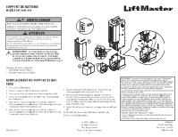
BATTERY HOLDER
MODEL 041-0405-000
WARNING
To prevent possible SERIOUS INJURY or DEATH, disconnect
electric power to operator BEFORE installing. ALL electrical
connections MUST be made by a qualified individual.
CAUTION
To prevent damage to the receiver/logic board, DO NOT touch
printed circuit board of replacement receiver/logic board during
installation.
ALWAYS wear protective gloves and eye protection when changing
the battery or working around the battery compartment.
WARNING:
This product can expose you to chemicals
including lead, which are known to the State of California to
cause cancer or birth defects or other reproductive harm.
For more information go to www.P65Warnings.ca.gov.
This service kit includes:
•
Battery Holder Assembly (1)
•
Blank Battery Holder Label
REPLACING THE BATTERY HOLDER
1. Disconnect power.
2.
Remove the lower front cover (A).
3.
Disconnect and remove the batteries from the battery
compartment (B).
4.
Disconnect the wires coming from the safety reversing sensors,
door control, door lock, and cable tension monitor (if installed)
from the logic board (C).
5.
Remove the 4 screws securing the battery holder to the main
chassis to remove it (D).
6.
Before discarding the old battery compartment, copy the printed
information from the label to the blank label provided on the new
battery compartment.
7.
Attach the replacement battery compartment to the main chassis
using the same 4 screws (D).
114-5926-000
© 2023, LiftMaster
All Rights Reserved
Tous droits réservés
Todos los derechos reservados
LiftMaster
300 Windsor Drive
Oak Brook, IL 60523
LiftMaster.com
NOTICE:
This device complies with Part 15 of the FCC rules and Industry Canada’s license-
exempt RSSs. Operation is subject to the following two conditions: (1) this device may not
cause harmful interference, and (2) this device must accept any interference received, including
interference that may cause undesired operation.
Any changes or modifications not expressly approved by the party responsible for compliance
could void the user’s authority to operate the equipment.
This device must be installed to ensure a minimum 20 cm (8 in.) distance is maintained between
users/bystanders and device.
This device has been tested and found to comply with the limits for a Class B digital device,
pursuant to part 15 of the FCC rules and Industry Canada ICES standard. These limits are
designed to provide reasonable protection against harmful interference in a residential
installation. This equipment generates, uses and can radiate radio frequency energy and, if not
installed and used in accordance with the instructions, may cause harmful interference to radio
communications. However, there is no guarantee that interference will not occur in a particular
installation. If this equipment does cause harmful interference to radio or television reception,
which can be determined by turning the equipment off and on, the user is encouraged to try to
correct the interference by one or more of the following measures:
•
Reorient or relocate the receiving antenna.
•
Increase the separation between the equipment and receiver.
•
Connect the equipment into an outlet on a circuit different from that to which the receiver is
connected.
•
Consult the dealer or an experienced radio/TV technician for help.
A
8.
Reconnect the wires coming from the safety reversing sensors,
door control, door lock, and cable tension monitor (if installed)
from the logic board (C). Route the long antenna through the
slot in the battery holder (E).
9.
Install the batteries and connect the battery connectors (B).
10. Replace the lower front cover on the operator (A).
11. Reconnect power.
B
D
E
C