Invacare RPS350-2 Owners Manual
Invacare RPS350-2 Manual
 |
View all Invacare RPS350-2 manuals
Add to My Manuals
Save this manual to your list of manuals |
Invacare RPS350-2 manual content summary:
- Invacare RPS350-2 | Owners Manual - Page 1
User Manual Stand Up Patient Lift RPS350-2 DEALER: This manual MUST be given to the user of the product. USER: BEFORE using this product, read this manual and save for future reference. For more information regarding Invacare products, parts, and services, please visit www.invacare.com - Invacare RPS350-2 | Owners Manual - Page 2
for use with Invacare products. SYMBOL LEGEND "ATTENTION, see instructions for use". WARNING - ALWAYS be aware of the Lift Arm. Injury to the patient and/or assistant may occur. 2010 "Date of Manufacture" Device contains Lead Acid batteries. DO NOT dispose of batteries in normal household - Invacare RPS350-2 | Owners Manual - Page 3
Maintenance ...9 Pinch Points ...9 SECTION 2-ASSEMBLY 10 Unpacking the Patient Lift ...10 Assembling the Mast Assembly to the Base...10 Attach the Leg Actuator to the Mast Assembly ...11 Attaching the Battery Charger Mounting Bracket to the Wall 12 Prepare the Patient Lift for Use...12 SECTION - Invacare RPS350-2 | Owners Manual - Page 4
Checklist...22 Cleaning the Sling and the Lift...22 Detecting Wear and Damage...22 Lubricating the Lift ...23 Adjusting the Base...23 Adjusting the Knee Pad Height ...23 Replacing the Mast Actuator ...24 Replacing the Leg Actuator...24 LIMITED WARRANTY 28 Stand Up Patient Lift 4 Part No. 1145811 - Invacare RPS350-2 | Owners Manual - Page 5
SPECIAL NOTES SPECIAL NOTES Signal words are used in this manual and apply to hazards or unsafe practices which could result in personal injury or while transmission is in progress. MAINTENANCE Maintenance MUST be performed ONLY by qualified personnel. Part No. 1145811 5 Stand Up Patient Lift - Invacare RPS350-2 | Owners Manual - Page 6
LABEL LOCATION LABEL LOCATION Stand Up Patient Lift 6 Part No. 1145811 - Invacare RPS350-2 | Owners Manual - Page 7
PRODUCT PARAMETERS PRODUCT PARAMETERS RPS350-2 Stand Up Patient Lift Height at Sling Hook-up - MAX.: Height at Sling Hook-up - MIN.: Base Width OPEN: Base Width CLOSED: Base Height (Clearance): Base Length: Overall Height: Overall Length: Overall Width: Caster Size (FRONT) Caster Size (REAR) Sling - Invacare RPS350-2 | Owners Manual - Page 8
removed and replaced, to ensure that it is properly attached before the patient is removed from a stationary object (bed, chair or commode). If the patient is in a wheelchair, secure the wheel locks in place to prevent the chair from moving forwards or backwards. Stand Up Patient Lift 8 Part No - Invacare RPS350-2 | Owners Manual - Page 9
click when mounting battery on the battery charger to confirm proper mounting. Otherwise, injury or damage may occur. Use the handles to push or pull the patient lift. Lifting the Patient Before positioning the legs of the stand up lift around the patient, make sure that the patient's feet are out - Invacare RPS350-2 | Owners Manual - Page 10
. ƽ WARNING Use only Invacare parts in the assembly of this patient lift. The base legs, the mast, boom, pump assembly and swivel bar are manufactured to specifications that assure correct alignment of all parts for safe functional operation. Assembling the Mast Assembly to the Base NOTE: The mast - Invacare RPS350-2 | Owners Manual - Page 11
. 3. Install the pin through the holes of the leg actuator and mast bracket and secure with hitch pin. Hitch Pin (not shown) Hand Control Mast Lift Arm Mast Bracket Pin Control Box Leg Actuator FIGURE 2.2 Attach the Leg Actuator to the Mast Assembly Part No. 1145811 11 Stand Up Patient Lift - Invacare RPS350-2 | Owners Manual - Page 12
LED will illuminate when power is applied to battery charger. Prepare the Patient Lift for Use 1. Plug the hand control, leg actuator and mast actuator into the connections on the bottom of the control box. 2. Check and tighten all hardware BEFORE use. Stand Up Patient Lift 12 Part No. 1145811 - Invacare RPS350-2 | Owners Manual - Page 13
. Thoroughly read the instructions in this owner's manual, observe a trained team of experts performing the lifting procedures and then perform the entire lift procedure several times with proper supervision and a capable individual acting as a patient. The legs of the stand up lift MUST be in the - Invacare RPS350-2 | Owners Manual - Page 14
damage may occur. 6. Place the battery on the control box. Push the top of the battery against the mounting bracket until there is an audible click. An audible "click" will be heard when properly installed (STEPS 3 and 6) FIGURE 3.4 Charging the Battery Stand Up Patient Lift 14 Part No. 1145811 - Invacare RPS350-2 | Owners Manual - Page 15
of moving parts to avoid injury. Invacare patient slings are made specifically for use with Invacare patient lifts. For the safety of the patient, DO NOT intermix patient slings and patient lifts of different manufacturers. Individuals that use the standing patient sling MUST be able to support the - Invacare RPS350-2 | Owners Manual - Page 16
is at the base of the spine and the patient's arms are outside the sling. Invacare does not recommend locking the rear casters of the stand up lift when lifting and transferring an individual. Doing so could cause the lift to tip and endanger the patient and assistants. Invacare recommends that the - Invacare RPS350-2 | Owners Manual - Page 17
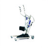
will be supported by the stand up lift. NOTE: The lower center of gravity provides stability making the patient feel more secure and the lift easier to move. Mast Handle Handgrip Knee Pad DETAIL "A" - WHEEL LOCK Wheel Lock Casters Moving the Patient Foot Plate FIGURE 4.2 Lifting the Patient - Invacare RPS350-2 | Owners Manual - Page 18
attachments each time the sling is removed and replaced to ensure that it is properly attached before the patient is removed from a surface. The use of one assistant is based on the evaluation of the health care professional for each individual case. Stand Up Patient Lift 18 Part No. 1145811 - Invacare RPS350-2 | Owners Manual - Page 19
side of the bed. 2. Press the UP button on the hand control to elevate the patient high enough to clear the arms of the commode chair. Their weight will be supported by the stand up lift. 3. Guide the patient onto the commode chair. This may require two assistants. 4. Press the down arrow button to - Invacare RPS350-2 | Owners Manual - Page 20
bed. ƽ WARNING Invacare recommends locking the rear swivel casters ONLY when positioning or removing the sling from around the patient. 3. Lock the rear swivel casters on the stand up lift. 4. Unhook the sling from all attachment points on the lift. 5. Instruct the patient to lift their feet off - Invacare RPS350-2 | Owners Manual - Page 21
lift arms. Legs don't open and close properly. Leg actuator may be worn or Refer to Replacing the Leg Actuator on damage. Spindle might be bent. page 24. NOTE: If problems are not remedied by the suggested means, please contact your dealer or Invacare. Part No. 1145811 21 Stand Up Patient Lift - Invacare RPS350-2 | Owners Manual - Page 22
the maintenance procedures described in this manual to keep your patient lift in continuous service. The Invacare Patient Lift is designed to provide a maximum of safe, efficient and satisfactory service with minimum care and maintenance. All parts of the Invacare Lift are made of the best grades - Invacare RPS350-2 | Owners Manual - Page 23
Lift The Invacare lift is designed for minimum maintenance. However, a six month check and lubrication should ensure continued safety and reliability. Keep lift the Base Knee Pad Adjustment Pin Adjustment Pin FIGURE 7.2 Adjusting the Knee Pad Height Part No. 1145811 23 Stand Up Patient Lift - Invacare RPS350-2 | Owners Manual - Page 24
25. 1. Remove the existing leg actuator. 2. Slide the replacement leg actuator into the slot in the base of the lift. 3. Perform the following to secure the leg actuator to the pivot bracket (Detail "A"): ƽ WARNING Ensure that there is sufficient room to put the patient lift on its side and the - Invacare RPS350-2 | Owners Manual - Page 25
the bottom of the control box. Leg Base Pivot Bracket Hitch Pin Hand Control Leg Actuator Pin Lift Arm Hitch Pin (not shown) Mast Bracket Pin Part No. 1145811 Mast Battery and Control Box Mast Actuator Leg Actuator Slot in Base FIGURE 7.4 Replacing the Leg Actuator 25 Stand Up Patient Lift - Invacare RPS350-2 | Owners Manual - Page 26
SECTION 7-MAINTENANCE NOTES Stand Up Patient Lift 26 Part No. 1145811 - Invacare RPS350-2 | Owners Manual - Page 27
NOTES SECTION 7-MAINTENANCE Part No. 1145811 27 Stand Up Patient Lift - Invacare RPS350-2 | Owners Manual - Page 28
, OR TO A PRODUCT DAMAGED BY CIRCUMSTANCES BEYOND INVACARE'S CONTROL, AND SUCH EVALUATION WILL BE SOLELY DETERMINED BY INVACARE. THE WARRANTY SHALL NOT APPLY TO PROBLEMS ARISING FROM NORMAL WEAR OR FAILURE TO ADHERE TO THE INSTRUCTIONS IN THIS MANUAL. THE FOREGOING WARRANTY IS EXCLUSIVE AND IN LIEU
-
 1
1 -
 2
2 -
 3
3 -
 4
4 -
 5
5 -
 6
6 -
 7
7 -
8
-
9
-
10
-
11
-
12
-
13
-
14
-
15
-
16
-
17
-
18
-
19
-
20
-
21
-
22
-
23
-
24
-
25
-
26
-
27
-
28
 |
 |

User Manual
DEALER:
This manual MUST be given to the user of the product.
USER:
BEFORE using this product, read this manual and save for future reference.
For more information regarding
Invacare products,
parts, and services,
please visit www.invacare.com
Stand Up Patient Lift
RPS350-2