Hitachi C8FSE Instruction Manual
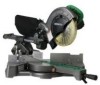
Hitachi C8FSE - 8-1/2" Sliding Compound Miter Saw Manual
 |
UPC - 717709012998
View all Hitachi C8FSE manuals
Add to My Manuals
Save this manual to your list of manuals |
Hitachi C8FSE manual content summary:
- Hitachi C8FSE | Instruction Manual - Page 1
Model C 8FSHE Modèle C 8FSE Modelo (Laser Marker and Light Equipment) (Marqueur laser et lumière) (Equipo con marcador láser y luz) Slide Compound Miter Saw Scie à onglets coulissante Ingletadora telescopica SAFETY INSTRUCTIONS AND INSTRUCTION MANUAL WARNING IMPROPER OR UNSAFE use of this power - Hitachi C8FSE | Instruction Manual - Page 2
MAINTENANCE 8 NAME OF PARTS 8 SPECIFICATIONS 9 ACCESSORIES 10 PAGE APPLICATIONS 10 PREPARATION BEFORE OPERATION 11 BEFORE USING 12 BEFORE CUTTING 13 PRACTICAL APPLICATIONS 18 SAW BLADE MOUNTING AND DISMOUNTING 26 MAINTENANCE AND INSPECTION 27 SERVICE AND REPAIRS 28 PARTS LIST 84 Fran - Hitachi C8FSE | Instruction Manual - Page 3
Instruction Manual. NEVER use this power tool in a manner that has not been specifically recommended by HITACHI keep the work place tamper-proof by installing locks on the doors and on more safely if it is operated at the rate for which it was designed. 7. ALWAYS moving parts. Always wear non-slip - Hitachi C8FSE | Instruction Manual - Page 4
injury or damage to the tool. 23. Never raise the saw blade from the workpiece until it has first come to a complete stop. 24. Always use outboard stands to provide support for long workpieces that overhang the table of the slide compound miter saw. 25. Always return the carriage to the full rear - Hitachi C8FSE | Instruction Manual - Page 5
in use. 23. Always use outboard stands to provide support for long workpieces that overhang the table of the slide compound miter saw. 24. Always operate the tool after ensuring the workpiece is fixed properly with a vise assembly. 25. The operating instructions provided with the tool shall direct - Hitachi C8FSE | Instruction Manual - Page 6
FOR YOUR OWN SAFETY READ THIS INSTRUCTION MANUAL BEFORE OPERATING THE SLIDE COMPOUND MITER SAW 1. Always wear eye protection when using the slide compound miter saw. 2. Always keep hands out of the path of the saw blade. 3. Never operate the saw without the guards in place. 4. Never perform any - Hitachi C8FSE | Instruction Manual - Page 7
in this Instruction Manual, including not using the power tool in wet environments. To keep the double insulation system effective, follow these precautions: * Only HITACHI AUTHORIZED SERVICE CENTER should disassemble or assemble this power tool, and only genuine HITACHI replacement parts should be - Hitachi C8FSE | Instruction Manual - Page 8
tool. NAME OF PARTS MODEL C8FSHE/MODEL C8FSE Gear case Spindle cover Motor head Handle Dust bag Hinge Light (Only C8FSHE) Holder (A) Laser marker (Only C8FSHE) Sub fence Vise assembly Fence (B) Saw blade Rotation direction Lower guard Fence (A) Indicator (For miter scale) Table insert - Hitachi C8FSE | Instruction Manual - Page 9
Model C8FSHE / C8FSE Motor Type Series commutator motor Power source Single-phase AC 60Hz Voltage (Volts) 120 Full-load current (Amp) 9.2 Laser Marker Maximum output - Hitachi C8FSE | Instruction Manual - Page 10
for this power tool are mentioned in this Instruction Manual. The use of any other attachment or accessory can be dangerous and could cause injury or mechanical damage. STANDARD ACCESSORIES 1 8-1/2" (216mm) TCT Saw blade (1 piece) 2 Dust bag (1 piece) 4 10mm BOX wrench (1 piece) 6 Side handle - Hitachi C8FSE | Instruction Manual - Page 11
bench surface. After adjustment, firmly tighten the 6mm bolt. Holder Adjust the holder until its bottom surface contacts the work bench surface. Move Fig. 5 2. Install the side handle (Fig. 6) Install the side handle that came enclosed with this unit. Turntable Side handle Fig. 6 Tighten 11 - Hitachi C8FSE | Instruction Manual - Page 12
Lowering the handle slightly will enable you to disengage the locking pin more easily and safely. The lock position of the locking pin is for carrying and storage only. Locking pin Pull Fig. 7 4. Installing the dust bag, holder, stopper and vises (The holder and stopper are optional accessories - Hitachi C8FSE | Instruction Manual - Page 13
bevel angle cutting. 2. Checking the saw blade lower limit position Check that the saw blade can be lowered 13/32" to 7/16" (10mm to 11mm) below the table insert as shown in Fig. 10-a. When you replace a saw blade with a new one, adjust the lower limit position so that the saw blade will not cut the - Hitachi C8FSE | Instruction Manual - Page 14
will not come in contact with the workpiece. 6mm Depth adjustment bolt Hinge Turn To adjust the lower limit position of the saw blade, follow the procedure (1) shown in Fig. 11. (1) Lower the motor head, and turn the 6 mm depth adjustment bolt and make adjustments so that there can be a clearance - Hitachi C8FSE | Instruction Manual - Page 15
tool is shipped from the factory, it is adjusted for 0°, pin on the direction shown in Fig. 13-a and incline the motor head to the left. When changing the bevel angle to the table and cause bodily harm. 7. Installing the holders ... (Optional accessory) The holders help keep longer workpieces - Hitachi C8FSE | Instruction Manual - Page 16
be aligned with the left side of the cutting width (saw blade) or the ink line on the right side. The laser line is adjusted to the width of the saw blade at the time of factory shipment. Adjust the positions of the saw blade and the laser line taking the following steps to suit the use of your - Hitachi C8FSE | Instruction Manual - Page 17
right side of the saw blade, align the laser line with the right side of the groove. Laser Line (3) After adjusting the position of the laser line, draw a with the laser line. When aligning the ink line, slide the workpiece little by little and secure it by vise at a position where the laser line - Hitachi C8FSE | Instruction Manual - Page 18
trigger. 2. Using the Vise Assembly (Standard accessory) (1) The vise assembly can be mounted on (2) The screw holder can be raised or lowered according to the Vise plate height of the confirm that the motor head (see Fig. 1) does not contact the vise assembly when it is lowered for cutting. If - Hitachi C8FSE | Instruction Manual - Page 19
Fig. 25 the width of the saw blade is the width of the cut. Therefore, slide the workpiece to the right (viewed from the operator's position) when length b is desired, or to the left when length a is desired. (Only Model C8FSHE) If a laser marker is used, align the laser line with the left side of - Hitachi C8FSE | Instruction Manual - Page 20
the slide securing knob (see Fig. 2), grip the handle and slide the saw blade forward. Then press down on the handle and slide the saw blade back during the cutting operation because the saw blade comes close to the side handle when the motor head is lowered. 7. Bevel cutting procedures Holder - Hitachi C8FSE | Instruction Manual - Page 21
operation halfway, start cutting after pulling back the motor head to the initial position. Starting from halfway, without pulling back, causes the lower guard to be caught in the cutting groove of the workpiece and to contact the saw blade. CAUTION: When cutting a workpiece of 1-15/16" (50mm - Hitachi C8FSE | Instruction Manual - Page 22
B lower surface Fig. 33 Wall 12 34 Inside corner Outside corner Fig. 34 The table below shows the miter angle and 4 in Fig. 34 (see Fig. 36; tilt the motor head to the left): 1 Turn the turntable to the right and set the Miter Angle as follows: * For 45° type crown moldings: 35 - Hitachi C8FSE | Instruction Manual - Page 23
the Miter Angle lower surface (B in saw blade. (1) Crown molding Stopper (L) and (R) (optional accessories) allow Crown molding Vise Ass'y Crown molding Stopper (R) (optional accessories) (optional accessories) easier cuts of crown molding without tilting the saw blade. 6mm Knob Install - Hitachi C8FSE | Instruction Manual - Page 24
bolt. Cutting depth adjustment procedure: (1) Lower the motor head, and turn the 6 mm depth adjustment bolt by hand. (Where the head of the 6 mm depth adjustment bolt contacts the hinge.) (2) Adjust to the desired cutting depth by setting the distance between the saw blade and the surface of the - Hitachi C8FSE | Instruction Manual - Page 25
the dust bag (Standard accessory) Dust bag (1) When the dust bag has become full of sawdust, dust will be blown out of the dust bag when the saw blade rotates. Check the dust bag periodically and empty it before it becomes full. Duct (2) During bevel and compound cutting, attach the dust bag at - Hitachi C8FSE | Instruction Manual - Page 26
to the left by standard accessorie's wrench (10mm box wrench) as indicated in Fig. 47-c. CAUTION: * A dust guide is installed inside behind the gear case. When removing or installing the saw blade, do not make contact with the dust guide. Contact may break or chip saw blade tips. * Confirm that the - Hitachi C8FSE | Instruction Manual - Page 27
motor are expendable parts. If the carbon brushes become excessively worn, motor trouble might occur. Therefore, inspect the carbon brushes periodically and replace them when they have become worn to the wear limit line as shown in Fig. 48. Also, keep the carbon brushes clean so that they will slide - Hitachi C8FSE | Instruction Manual - Page 28
Periodically remove chips, dust and other waste material from the surface of the power tool, especially from the inside of the lower guard with a damp, soapy cloth. To avoid a malfunction of the motor, protect it from contact with oil or water. (Only Model C8FSHE) If the laser line becomes invisible - Hitachi C8FSE | Instruction Manual - Page 29
d'une manière qui n'est pas spécifiquement recommandée par HITACHI. SIGNIFICATION DES MOTS D'AVERTISSEMENT AVERTISSEMENT indique des situations potentiellement dangereuses LES AVERTISSEMENTS ET TOUTES LES INSTRUCTIONS D'UTILISATION DU MANUEL AVANT DE METTRE L'OUTIL EN SERVICE OU DE L'ENTRETENIR : - Hitachi C8FSE | Instruction Manual - Page 30
la sécurité. Toujours suivre les instructions de graissage et de remplacement des accessoires n'est pas complètement arrêtée. 24. Toujours utiliser des supports extérieurs pour assurer la stabilité des longues pièces rentre toujours pas, faire installer une prise appropriée par un électricien qualifié. Ne pas - Hitachi C8FSE | Instruction Manual - Page 31
et se familiariser avec les consignes de sécurité et les instructions d'utilisation de l'OUTIL ELECTRIQUE avant de l'utiliser. 2. Toujours graisse. Tenir l'outil fermement pendant le travail. 23. Toujours utiliser des supports extérieurs pour assurer la stabilité des longues pièces qui dépassent - Hitachi C8FSE | Instruction Manual - Page 32
TOUTE SÉCURITÉ, NE JAMAIS VIOLER LES CONSIGNES SUIVANTES: 1. Ne jamais utiliser l'OUTIL ELECTRIQUE si l'on ne comprend pas bien les instructions de ce manuel. 2. Ne jamais s'éloigner de l'OUTIL ELECTRIQUE sans débrancher auparavant son cordon d'alimentation. 3. Ne jamais utiliser l'OUTIL ELECTRIQUE - Hitachi C8FSE | Instruction Manual - Page 33
de 8-1/2" (216mm). 9. La un centre de service après-vente Hitachi agréé. UTILISER LE CORDON DE RALLONGE APPROPRIÉ Utiliser exclusivement un cordon de rallonge en bon état. Lorsqu'on utilise un cordon de rallonge, veiller à ce qu'il soit suffisamment lourd pour supporter - Hitachi C8FSE | Instruction Manual - Page 34
Français CONSERVER CES INSTRUCTIONS ET LES METTRE A LA DISPOSITION DES AUTRES UTILISATEURS ET PROPRIETAIRES DE CET OUTIL! 34 - Hitachi C8FSE | Instruction Manual - Page 35
NOM DES PIÈCES MODÈL C8FSHE/MODÈL C8FSE Carter Couvercle d'axe Tête de moteur Poignée Sac à copeaux Charnière Lumière (C8FSHE seulement) Support (A) Marqueur à laser (C8FSHE seulement) Garde secondaire Ensemble d'étau Garde (B) Lame Sens de rotation Guide inférieur Garde (A) Indicateur (Pour - Hitachi C8FSE | Instruction Manual - Page 36
C8FSHE / C8FSE Moteur Type Moteur à commutateur série Alimentation Courant alternatif monophasé 60 Hz Tension (volts) 120 Courant à pleine charge (Amp) 9.2 Marqueur laser Puissance de sortie maximum - Hitachi C8FSE | Instruction Manual - Page 37
dommages mécaniques. ACCESSOIRES STANDARD 1 lame TCT de 8-1/2" (216mm) (1) 2 Sac à copeaux (1) 4 Clé à page 42. Fig. 3 ACCESSOIRES EN OPTION........vendus séparément 1 Support de rallonge et butée (No. de code 321553) 2 Lame TCT part de HITACHI. APPLICATIONS Cadres en bois et en aluminium. 37 - Hitachi C8FSE | Instruction Manual - Page 38
L'UTILISATION Avant de mettre l'outil électrique en service, effectuer les préparations suivantes : 1. Installation 5-13/16"(148mm) Socle Boulon de 5/16 Support Régler le support jusqu'à ce que sa surface inférieure soit en contact avec la surface du banc. Déplacer Fig. 5 Socle 2. Installer - Hitachi C8FSE | Instruction Manual - Page 39
goupille de verrouillage ne doit servir que pour le transport Goupille de verrouillage Tirer et le remisage. Fig. 7 4. Installer le sac à copeaux, le support, la butée et les étaux (Le support et la butée sont des accessoires en option.) Fixer le sac à copeaux et l'ensemble d'étau comme indiqu - Hitachi C8FSE | Instruction Manual - Page 40
s'assurer que la lame ne présente pas d'instabilité évidente ; sinon, cela risque de provoquer des vibrations et un accident. AVANT LA COUPE 1. Installation de la plaque d'insertion Pièce Vis de 6mm Lame Plaque d'insertion Vis de 6mm Pièce Lame Plaque d'insertion [Coupe à angle droit] Fig - Hitachi C8FSE | Instruction Manual - Page 41
Français 2. Vérification de la position limite inférieure de la lame de scie S'assurer que la lame de scie peut être abaissée de 13/32" à 7/16" (10 à 11mm) en dessous de la plaque d'insertion de table, comme le montre la Fig. 10-a. Lorsque l'on remplace une lame de scie par une lame neuve, régler - Hitachi C8FSE | Instruction Manual - Page 42
èce risque d'être éjectée de la table et de blesser quelqu'un. 7. Installation des supports ... (Accessoires en option) Bouton de boulonnage de 6mm (accessoire en option) Equerre Support (accessoire en option) Les supports permettent de fixer et de stabiliser les pièces longues pendant la coupe - Hitachi C8FSE | Instruction Manual - Page 43
17-3/4" (280 à 450mm). Pour installer la butée, la fixer au support à l'aide du bouton de boulonnage de laser (Uniquement pour le modèle C8FSHE) AVERTISSEMENT: * Avant de brancher la fiche du cordon d'alimentation sur une prise secteur, s'assurer que l'outil est le marqueur à laser sont hors service - Hitachi C8FSE | Instruction Manual - Page 44
scie Marquage (prémarquage) Largeur de coupe Fig. 19 (1) Allumer le marqueur laser et marquer une rainure de 3/16" (5mm) environ de profondeur sur la pi encre sur le côté gauche de la lame de scie, il faut aligner la ligne laser avec le côté gauche de la rainure. (Fig. 20) Si on travaille avec la - Hitachi C8FSE | Instruction Manual - Page 45
* Pour éviter tout risque de blessure, ne jamais retirer ni installer la pièce sur la table pendant que l'outil fonctionne. d'étau le réglage, resserrer fermement le boulon à ailettes de 6mm (B) et fixer le support de vis. (3) Tourner le bouton supérieur et fixer solidement la pièce en place - Hitachi C8FSE | Instruction Manual - Page 46
de face) Fig. 25 (Uniquement pour le modèle C8FSHE) Si le marqueur laser est utilisé, aligner la ligne laser sur le côté gauche de la lame de scie, puis minces (Coupe à pression simple) Poignée Glisser la charnière sur le support (A), et serrer le bouton de fixation de glissière comme (Voir Fig - Hitachi C8FSE | Instruction Manual - Page 47
Français 6. Coupe de pièces larges (Coupe avec chariot) 1 Tirer vers l'avant 3 Pousser vers l'arrière pour couper Poignée (1) Pièces d'une hauteur allant jusqu'à 2-9/16" (65mm) et d'une largeur allant jusqu'à 12-1/4" (312mm): Desserrer le bouton de fixation de glissière et incliner la lame vers - Hitachi C8FSE | Instruction Manual - Page 48
latérale insuffisamment serrée, donnera une mauvaise précision. Fig. 32 9. Procédures de coupe mixte La coupe mixte s'effectue en suivant les instructions de 7 et 8 ci-dessus. Pour les dimensions maximales de la coupe mixte, voir le tableau des "SPÉCIFICATIONS" à la page 36. ATTENTION: Toujours - Hitachi C8FSE | Instruction Manual - Page 49
Français Réglage d'une coupe d'onglet Si la plaque tournante est réglée sur l'un des angles décrits, déplacer la poignée latérale de réglage de la plaque tournante légèrement vers la droite ou vers la gauche pour stabiliser la position et aligner correctement l'échelle d'onglet et l'extrémité de l' - Hitachi C8FSE | Instruction Manual - Page 50
permettent des (accessoire en option) coupes plus faciles de corniches complexes sans inclinaison Bouton de boulonnage de 6mm de la lame de scie. Les installer sur la base, de chaque côté, comme le montre la Fig. 40-a. Après les avoir introduits, serrer les boutons de boulonnage de 6mm sur les - Hitachi C8FSE | Instruction Manual - Page 51
à l'une des extrémités de la pièce, retirer la section inutile avec un ciseau 12. Utilisation de la lumière (Uniquement modèle C8FSHE) AVERTISSEMENT: Vérifiez que l'unité et la lumière sont éteintes avant de raccorder le cordon à la prise d'alimentation. La lentille lumineuse atteint des temp - Hitachi C8FSE | Instruction Manual - Page 52
de lumière Commutatear (1) Insérez la prise de l'unité dans une fiche d'alimentation. (Pour la lumière) (2) Mettre en marche le marqueur de laser. (3) Placez l'interrupteur en position supérieure (ON) pour allumer la lumière, et en position inférieure (OFF) pour l'éteindre (Voir Fig. 43). Lentille - Hitachi C8FSE | Instruction Manual - Page 53
de 10 mm Fig. 47-a Verrou en fuseau Serrer Boulon Fig. 47-b Lame Desserrer Rondelle (D) Boulon Guide inférieur Fig. 47-c Rondelle (D) Fig. 47-d Rondelle (D) (4) Soulever le garde inférieur et installer la lame. AVERTISSEMENT: Lors du montage de la lame de scie, s'assurer que la marque de - Hitachi C8FSE | Instruction Manual - Page 54
installer des lames de scie de plus de 8-1/2" (216mm) de diamètre. Toujours installer des lames de scie d'un diamètre égal ou inférieur à 81/2" (216mm No. 21 représente les deux derniers chiffres du no. de code des balais carbone. Fente de tournevis Fig. 48 Fig. 49 3. A propos de l'entretien du - Hitachi C8FSE | Instruction Manual - Page 55
* Section rotative du support (A) 8. Nettoyage Nettoyer modèle C8FSHE) Si la ligne laser devient invisible en raison laser, essuyer et nettoyer la fenêtre avec un chiffon sec ou un chiffon doux humecté d'une solution d'eau savonneuse, etc. SERVICE SERVICE APRES-VENTE D'OUTILS ELECTRIQUES HITACHI AGREE - Hitachi C8FSE | Instruction Manual - Page 56
, los riesgos están identificados con ADVERTENCIAS en dicha herramienta y en este Manual de instrucciones. No utilice NUNCA esta herramienta eléctrica de ninguna forma que no esté específicamente recomendada por HITACHI. SIGNIFICADO DE LAS PALABRAS DE SEÑALIZACIÓN ADVERTENCIA indica situaciones - Hitachi C8FSE | Instruction Manual - Page 57
SIEMPRE LAS HERRAMIENTAS EN PERFECTAS CONDICIONES. Guarde siempre las herramientas afiladas y limpias sobre los accesorios recomendados, consulte el manual de instrucciones. Para evitar lesiones, ANTES DE UTILIZAR LA HERRAMIENTA, COMPRUEBE SI TIENE PARTES DAÑADAS. Compruebe siempre si el protector y - Hitachi C8FSE | Instruction Manual - Page 58
tomacorriente, póngase en contacto con un electricista cualificado para que le instale el tomacorriente apropiado. No cambie nunca el enchufe del cable de : 1. Antes de intentar utilizar esta HERRAMIENTA ELÉCTRICA, lea este manual y familiarícese con las normas de seguridad y las instrucciones de - Hitachi C8FSE | Instruction Manual - Page 59
motor estén completamente abiertos. 21. Antes de comenzar a cortar, espere siempre hasta que el motor ÉCTRICA para aplicaciones no especificadas en este manual. 5. No utilice nunca la herramienta con las partes móviles. 6. No acerque las manos a la hoja de sierra. 7. No toque nunca las partes móviles - Hitachi C8FSE | Instruction Manual - Page 60
, ANTES DE UTILIZAR LA INGLETADORA TELESCOPICA, LEA ESTE MANUAL DE INSTRUCCIONES. 1. Para utilizar esta ingletadora telescopica, trabajo de mantenimiento. 8. El diámetro de la hoja de sierra es de 8-1/2" (216mm). 9. La velocidad sin carga es de 5,500/min. 10. Para reducir el riesgo por Hitachi. 60 - Hitachi C8FSE | Instruction Manual - Page 61
este Manual de instrucciones HITACHI. * Limpie el exterior de la herramienta eléctrica solamente con un paño suave humedecido en agua jabonosa, y después séquela bien. * No utilice disolventes, gasolina, ni diluidor de pintura para limpiar las partes de plástico, ya que podría disolverlas. ¡GUARDE - Hitachi C8FSE | Instruction Manual - Page 62
ELÉCTRICA. Algunas ilustraciones de este manual pueden mostrar detalles o dispositivos diferentes a los de su propia HERRAMIENTA ELÉCTRICA. NOMENCLATURA DE PARTES MODELO C8FSHE/MODELO C8FSE Caja de engranajes Cubierta del huso Cabezal Empuñadura del motor Bolsa para el polvo Bisagra Luz - Hitachi C8FSE | Instruction Manual - Page 63
Español ESPECIFICACIONES Ítem Modelo: C8FSHE / C8FSE Motor Tipo Motor conmutador en serie Fuente de alimentación Monofásica, CA, Medio de láser Diodo láser Hoja de sierra aplicable Diámetro exterior: 8-1/2" (216mm) Diámetro del orificio: 5/8" (15.9mm) Velocidad sin carga 5,500/min - Hitachi C8FSE | Instruction Manual - Page 64
trabajo, incluso aunque la cabeza del motor se encuentre en la posición del ctrica se mencionan en este Manual de instrucciones. La utilizaci ESTÁNDAR 1 Hoja de sierra TCT de 8-1/2" (216mm) (1 pieza) 2 Bolsa para el polvo (1 parte de HITACHI. APLICACIONES Puertas corredizas de madena y aluminio. 64 - Hitachi C8FSE | Instruction Manual - Page 65
un banco de trabajo con grosor de 1" (25mm). El soporte (B) fijado a la parte posterior de la base ayuda a estabilizar la herramienta eléctrica. Perno de 6mm Ajuste del banco de trabajo. Fig. 5 Mueva 2. Instale el asa lateral (Fig. 6) Instale el asa lateral proporcionada con esta unidad. Mesa - Hitachi C8FSE | Instruction Manual - Page 66
Español 3. Liberación del pasador de bloqueo Cuando la herramienta eléctrica esté preparada para transportarse, sus partes principales estarán aseguradas mediante el pasador de bloqueo. Mueva ligeramente la empuñadura de forma que el pasador de Empuñadura bloqueo pueda desenganchar. NOTA: - Hitachi C8FSE | Instruction Manual - Page 67
Español 7. Compruebe la posición del límite inferior de la hoja de sierra. Aunque fue ajustada antes del envío, compruebe cuidadosamente la altura de la hoja de sierra. Confirme que la hoja de sierra pueda bajarse de 13/32" a 7/16" (10 a 11mm) por debajo del inserto de la mesa. Con respecto a los - Hitachi C8FSE | Instruction Manual - Page 68
la posición de límite inferior de manera que la base de la cabeza del motor (consulte la Fig. 10-a) no entre en contacto con la pieza de trabajo. a 3 mm) entre la posición de límite inferior de la cabeza del motor y la parte superior de la pieza de trabajo en la posición de límite inferior de la - Hitachi C8FSE | Instruction Manual - Page 69
el ángulo de bisel 45° hacia la izquierda y más, tire del pasador de fijación en el sentido mostrado en la Fig. 13-a e incline la cabeza del motor hacia la izquierda. Cuando cambie el ángulo de bisel hacia la derecha, tire del pasador de fijación en el sentido mostrado en la Fig. 13 - Hitachi C8FSE | Instruction Manual - Page 70
de 6mm (accesorio opcional) Perno de ajuste de la altura (accesorio opcional) 9. Posición de ajuste de la línea de láser (Sólo modelo C8FSHE) ADVERTENCIA: * Antes de enchufar la clavija de alimentación en el tomacorriente, asegúrese de que el cuerpo principal y el marcador láser se encuentren - Hitachi C8FSE | Instruction Manual - Page 71
. En tales casos, trasládese a un sitio protegido de la luz del sol. * No tire con fuerza del cordón provisto detrás de la cabeza del motor ni enganche su dedo o algún objeto alrededor del mismo; de lo contrario, el cordón se podría salir y el marcador láser no se podrá encender. Línea - Hitachi C8FSE | Instruction Manual - Page 72
encendido accidental de la herramienta eléctrica o la utilización por parte de personas no autorizadas (especialmente los niños). Para evitar la mesa y causar lesiones serias. PRECAUCIÓN: Confirme siempre que la cabeza del motor (consulte la Fig. 1) no entre en contacto con el conjunto de tornillo - Hitachi C8FSE | Instruction Manual - Page 73
longitud b, o hacia la izquierda cuando desee la longitud a. (Sólo modelo C8FSHE) Si se utiliza un marcador láser, alinee la línea de láser parte superior de la mesa giratoria, y luego realice el paso siguiente. * Una operación de corte continua podrá provocar la sobrecarga del motor. Toque el motor - Hitachi C8FSE | Instruction Manual - Page 74
manivela de abrazadera e incline la hoja de sierra hacia la izquierda o la derecha. Cuando incline la cabeza del motor hacia la derecha, tire del pasador de fijación hacia la parte posterior. (2) Ajuste el ángulo de inclinación hasta el valor deseado observando la escala de ángulos de bisel y el - Hitachi C8FSE | Instruction Manual - Page 75
con un bisel de 5° hacia la izquierda ajuste la posición del límite inferior de la cabeza del motor de forma que quede a 5/64 a 1/8" (2 a 3mm) en la posición del límite de trabajo con la mano derecha o izquierda y córtela deslizando la parte redonda de la sierra hacia atrás con la mano izquierda. Es - Hitachi C8FSE | Instruction Manual - Page 76
Español 10. Procedimientos de corte con moldura en vértice En la Fig. 33 se muestran los tipos de moldura en vértice con ángulos de 38° y 45°. Con respecto a las molduras en vértice típicas, consulte la Fig. 34. A Superficie superior Techo Techo Pared B Superficie inferior Fig. 33 Pared 12 34 - Hitachi C8FSE | Instruction Manual - Page 77
Español (1) Ajuste para cortar molduras en vértice a los posiciones 1 y 4 de la Fig. 34 (consulte la Fig. 36, incline la cabeza hacia la izquierda): 1 Gire la mesa giratoria hacia la derecha y ajuste el ángulo de ingletes de la forma siguiente: * Para molduras en vértice de tipo de 45°: 35.3° ( - Hitachi C8FSE | Instruction Manual - Page 78
o la hoja de sierra podría entrar en contacto con la escuadra de guía secundaria, y producir lesiones. PRECAUCION: Siempre compruebe que la cabeza del motor (véase Fig.1) no haga contacto con el conj. de tornillo de carpintero para moldura en vértice (B) cuando lo baje para realizar el corte. Si - Hitachi C8FSE | Instruction Manual - Page 79
la pieza de trabajo, quite la parte innecesaria con un formón. 12.Utilización de la luz (Sólo Modelo C8FSHE) ADVERTENCIA: Compruebe para determinar que carpintero. Esto causará el corte ineficaz y posiblemente la sobrecarga del motor. Cuando corte tales materiales, utilice un tablón de madera para - Hitachi C8FSE | Instruction Manual - Page 80
Español 14. Forma de utilizar la bolsa para el polvo (Accesorio estándar) Bolsa para el polvo (1) Cuando la bolsa para el polvo esté llena de polvo, dicho polvo saldrá soplado de la bolsa para el polvo cuando gire la hoja de sierra. Compruebe periódicamente y vacíe la bolsa para el polvo antes de - Hitachi C8FSE | Instruction Manual - Page 81
de diámetro superior a 8-1/2" (216mm). Instale siempre las hojas de sierra de 8-1/2" (216mm) de diámetro o menos. MANTENIMIENTO , y otra desgastada puede causar la operación inefectiva o la posible sobrecarga del motor. PRECAUCIÓN: No utilice nunca una hoja de sierra mellada. Cuando la hoja de - Hitachi C8FSE | Instruction Manual - Page 82
ás materiales de la superficie de la herramienta eléctrica, sobre todo de la parte interior del protector inferior. Para evitar el mal funcionamiento del motor, protéjalo contra el aceite y el agua. (Sólo modelo C8FSHE) Si la línea de láser se volviera invisible debido a astillas u otras impurezas - Hitachi C8FSE | Instruction Manual - Page 83
doble aislamiento, todos los trabajos de servicio (excepto el mantenimiento rutinario) deberán realizarse SOLAMENTE EN UN CENTRO DE REPARACIONES DE HERRAMIENTAS ELÉCTRICAS AUTORIZADO POR HITACHI. NOTA: Las especificaciones están sujetas a cambio sin previo aviso sin ninguna obligación por - Hitachi C8FSE | Instruction Manual - Page 84
C8FSHE 84 - Hitachi C8FSE | Instruction Manual - Page 85
C8FSHE 85 - Hitachi C8FSE | Instruction Manual - Page 86
C8FSHE 86 - Hitachi C8FSE | Instruction Manual - Page 87
) D5 × 25 NYLOCK BOLT (A) M8 × 25 HOLDER (A) GUARD ASS'Y TAPPING SCREW (W/FLANGE) D4 × 16 CORD ARMOR D10.1 CORD CLIP CORD BUSH HOUSING ASS'Y NAME PLATE MACHINE SCREW (W/WASHERS) M5 × 40 HEX. SOCKET SET SCREW M5 × 8 BRUSH HOLDER CARBON BRUSH BRUSH CAP TAPPING SCREW (CLASS 2) D4 × 14 TAPPING SCREW - Hitachi C8FSE | Instruction Manual - Page 88
619 620 621 622 623 624 625 626 627 628 629 630 631 632 633 PART NAME RUBBER BUSHING ARMATURE ASS'Y KNOB BOLT M6 × 37 LOCK SPRING NYLOCK BOLT M8 HITACHI PLATE BOLT (W/WASHER) M6 × 16 DUST GUIDE GUIDE HOLDER BOLT (LEFT HAND) W/WASHER M7 × 17.5 TCT SAW BLADE FLAT HD. SCREW M4 × 10 COVER LOWER GUARD - Hitachi C8FSE | Instruction Manual - Page 89
C8FSE 89 - Hitachi C8FSE | Instruction Manual - Page 90
C8FSE 90 - Hitachi C8FSE | Instruction Manual - Page 91
C8FSE 91 - Hitachi C8FSE | Instruction Manual - Page 92
SOCKET SET SCREW M5 × 8 BRUSH HOLDER CARBON BRUSH BRUSH CAP TAPPING SCREW (WFLANGE) D4 × 20 HANDLE COVER CONNECTOR INTERNAL WIRE (G) SWITCH CAP SPRING LOCK LEVER FAN GUIDE HEX. HD. TAPPING SCREW D4 × 60 BRUSH TERMINAL STATOR ASS'Y BALL BEARING 608VVC2PS2L DUST SEAL BALL BEARING 6000VVCMPS2L BEARING - Hitachi C8FSE | Instruction Manual - Page 93
PART NAME BOLT (LEFT HAND) W/WASHER M7 × 17.5 TCT SAW BLADE FLAT HD. SCREW M4 × 10 COVER LOWER GUARD RETURN SPRING SPINDLE ASS'Y BALL BEARING 6003VVCM BEARING HOLDER BALL BEARING 608VVC2PS2L WASHER (D) MACHINE SCREW M5 × 20 SPRING WASHER M5 WASHER (G) BOX WRENCH 10MM DUST BAG 25 GUIDE ASS'Y Q'TY 1 1 2 - Hitachi C8FSE | Instruction Manual - Page 94
94 - Hitachi C8FSE | Instruction Manual - Page 95
95 - Hitachi C8FSE | Instruction Manual - Page 96
WARNING: Some dust created by power sanding, sawing, grinding, drilling, and other construction activities contains como las máscaras para el polvo especialmente diseñados para eliminar las partículas minúsculas. Issued by Hitachi Koki Co., Ltd. Shinagawa Intercity Tower A, 15-1, Konan 2-chome,
-
 1
1 -
 2
2 -
 3
3 -
 4
4 -
 5
5 -
 6
6 -
 7
7 -
8
-
9
-
10
-
11
-
12
-
13
-
14
-
15
-
16
-
17
-
18
-
19
-
20
-
21
-
22
-
23
-
24
-
25
-
26
-
27
-
28
-
29
-
30
-
31
-
32
-
33
-
34
-
35
-
36
-
37
-
38
-
39
-
40
-
41
-
42
-
43
-
44
-
45
-
46
-
47
-
48
-
49
-
50
-
51
-
52
-
53
-
54
-
55
-
56
-
57
-
58
-
59
-
60
-
61
-
62
-
63
-
64
-
65
-
66
-
67
-
68
-
69
-
70
-
71
-
72
-
73
-
74
-
75
-
76
-
77
-
78
-
79
-
80
-
81
-
82
-
83
-
84
-
85
-
86
-
87
-
88
-
89
-
90
-
91
-
92
-
93
-
94
-
95
-
96
 |
 |

SAFETY INSTRUCTIONS AND INSTRUCTION MANUAL
WARNING
IMPROPER OR UNSAFE
use of this power tool can result in death or serious bodily injury!
This manual contains important information about product safety. Please read and understand
this manual BEFORE operating the power tool. Please keep this manual available for other
users and owners before they use the power tool. This manual should be stored in safe place.
INSTRUCTIONS DE SECURITE ET MODE D’EMPLOI
AVERTISSEMENT
Une utilisation
INCORRECTE OU DANGEREUSE
de cet outil mo
torisé peut entraîner la mort ou de
sérieuses blessures corporelles!
Ce mode d’emploi contient d’importantes informations à propos de la sécurité de ce produit.
Prière de lire et de comprendre ce mode d’emploi AVANT d’utiliser l’outil motorisé. Garder ce
mode d’emploi à la disponibilité des autres utilisateurs et propriétaires avant qu’ils utilisent
l’outil motorisé. Ce mode d’emploi doit être conservé dans un en
droit sûr.
INSTRUCCIONES DE SEGURIDAD Y MANUAL DE INSTRUCCIONES
ADVERTENCIA
¡La utilización
INAPROPIADA O PELIGROSA
de esta herramienta eléctrica puede resultar en lesiones
de gravedad o la muerte!
Este manual contiene información importante sobre la seguridad del producto. Lea y comprenda este
manual ANTES de utilizar la herramienta eléctrica. Guarde este manual para que puedan leerlo otras
personas antes de utilizar la herramienta eléctrica. Este manual debe ser guardado en un lugar seguro.
DOUBLE INSULATION
DOUBLE ISOLATION
AISLAMIENTO DOBLE
Model
Slide Compound Miter Saw
Modèle
Scie à onglets coulissante
Modelo
Ingletadora telescopica
C 8FSHE
C 8FSE
(Laser Marker and Light Equipment)
(Marqueur laser et lumière)
(Equipo con marcador láser y luz)