Garmin GC 14 Installation Instructions
Garmin GC 14 Manual
 |
View all Garmin GC 14 manuals
Add to My Manuals
Save this manual to your list of manuals |
Garmin GC 14 manual content summary:
- Garmin GC 14 | Installation Instructions - Page 1
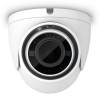
GC™ 14 INSTALLATION INSTRUCTIONS Getting Started WARNING See the Important Safety and Product Information guide in the product box for product warnings and other important information. Mounting Considerations You can mount the camera upside-down or sideways. You can reverse - Garmin GC 14 | Installation Instructions - Page 2
any chartplotters that do not have isolated power grounds. Installation Diagram GC 14 1 A fuse or circuit breaker (not included)1 12 Vdc power source BNC to BNC coaxial video cable (not included) Compatible Garmin chartplotter Composite video ground loop isolator (not included) 1 You must connect - Garmin GC 14 | Installation Instructions - Page 3
GC 14 1 A fuse or circuit breaker (required, not included)1 12 Vdc power source BNC to BNC coaxial video cable (not included) Network cable Power-over-Ethernet isolation coupler (GPN 010-10580-10) Garmin on your chartplotter. See your chartplotter manual for instructions. 1 You must connect the - Garmin GC 14 | Installation Instructions - Page 4
on your chartplotter. See your chartplotter manual for instructions. Camera is Not Working and the Garmin Ltd. or its subsidiaries Garmin®, the Garmin logo, and GPSMAP® are trademarks of Garmin Ltd. or its subsidiaries, registered in the USA and other countries. GC™ is a trademark of Garmin
-
 1
1 -
 2
2 -
 3
3 -
 4
4
 |
 |

GC
™
14
INSTALLATION
INSTRUCTIONS
Getting Started
WARNING
See the
Important Safety and Product Information
guide in the product box for product warnings and other
important information.
Mounting Considerations
You can mount the camera upside-down or sideways. You can reverse the camera image to use in rearview
mode. See your chartplotter owner's manual for instructions.
You should mount the camera in a location where it is
•
not an obstacle in doorways or walkways.
•
not exposed to extreme temperatures.
•
not exposed to gas or oil.
•
not exposed to radioactivity.
•
not facing into direct sunlight or a direct reflection of sunlight.
Tools Needed
•
1 A fuse or circuit breaker
•
Drill and 2 mm (
3
/
32
in.) drill bit
Mounting the Camera
1
Secure the template
to the mounting location.
2
Using a 2 mm (
3
/
32
in.) drill bit, drill the pilot holes.
3
Adjust the dome base
to the correct orientation for your desired camera tilt.
4
Secure the dome base to the mounting location using the included tapping screws
.
5
Insert the camera
into the dome base.
6
Secure the set screws
into the dome front
using the included wrench.
GUID-F3AB61D3-A701-4DF6-A841-B96657F5BE46 v3
April 2021