Dell W-Series 205H W-AP205H Access Point Installation Guide
Dell W-Series 205H Manual
 |
View all Dell W-Series 205H manuals
Add to My Manuals
Save this manual to your list of manuals |
Dell W-Series 205H manual content summary:
- Dell W-Series 205H | W-AP205H Access Point Installation Guide - Page 1
and 5 GHz 802.11n/ac functionality, while simultaneously supporting existing 802.11a/b/g wireless services. The W-AP205H access point can be attached to Refer to the Dell Networking W-Series ArubaOS Quick Start Guide for instructions on locating and connecting to the controller. Identifying Specific - Dell W-Series 205H | W-AP205H Access Point Installation Guide - Page 2
the manufacturer's instructions, may cause 第十二條 第十四條 NOTE: Expected Service Life 5 years. NOTE: Guide Contacting Dell Web Site Support Main Website Contact Information Support Website Documentation Website dell.com dell.com/contactdell dell.com/support dell.com/support/manuals
-
 1
1 -
 2
2
 |
 |

Dell Networking W-AP205H Access Point
Installation Guide
The Dell Networking W-AP205H access point is a high-performance dual-radio wireless and
wired access point for hospitality and branch deployments.
This device combines high-performance wireless mobility with Gigabit wired local access to
deliver secure network access to dormitories, hotel rooms, classrooms, medical clinics, and
multi-tenant environments. MIMO (Multiple-Input, Multiple-Output) technology enables
the W-AP205H access point to provide wireless 2.4 GHz 802.11n and 5 GHz 802.11n/ac
functionality, while simultaneously supporting existing 802.11a/b/g wireless services.
The W-AP205H access point can be attached to a wall box using the bracket provided, or
converted into a desk-mounted remote access point for branch office deployments using the
AP-205H-MNTR desk mount kit (sold separately).
The W-AP205H access point works in conjunction with a Dell Networking W-Series
controller.
The W-AP205H access point provides the following capabilities:
Dual wireless transceivers
IEEE 802.11a/b/g/n/ac operation as a wireless access point
IEEE 802.11a/b/g/n/ac operation as a wireless air monitor, spectrum analyzer
Centralized management configuration and upgrades through a Dell Controller
Compatibility with IEEE 802.3af/at PoE
Supports PoE-in on E0 port (only)/PoE-out on E3 port (only)
Support for selected USB peripherals
Package Contents
W-AP205H Access Point
Single Gang Wall-box Mounting Bracket
2x #6-32 Machine Screw
T8H Torx Security Screw
Installation Guide (this document)
Hardware Overview
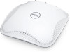
Figure 1
Front View of AP
LED
The W-AP205H access point is equipped with two LEDs in the front. The top LED indicates
the status of the AP as Power Sourcing Equipment (PSE) enabling PoE-out on the E3 port.
The bottom LED indicates the operational status of the AP.
Console Port
The W-AP205H access point is equipped with a serial console port at the back (
Figure 2
). The
port allows connecting the AP to a serial terminal or a laptop for direct local management. This
port located at the back of the W-AP205H access point is a 4-pin connector with removable
dust cover. An optional serial adapter cable (AP-CBL-SER) compatible with the W-AP205H
access point is sold separately.
Figure 2
Back View of AP
Ethernet Ports
The W-AP205H access point is equipped with a total of four active Ethernet ports (E0-E3).
E0 port, located at the back of the AP (
Figure 2
), is a 10/100/1000 Base-T (RJ-45) auto-
sensing, MDI/MDX wired-network uplink connectivity port. It supports IEEE 802.3af/
802.3at Power over Ethernet (PoE), accepting 48VDC (nominal) as a standard defined
Powered Device (PD) from a Power Sourcing Equipment (PSE) such as a PoE midspan
injector or network infrastructure that supports PoE.
E1-E3 ports, located at the bottom of the AP (
Figure 3
), are 10/100/1000 Base-T (RJ-45)
auto-sensing, MDI/MDX wired-network downlink connectivity ports. They are used to
provide secure network connectivity to wired devices. Only the E3 port supports PoE-out
functionality, supplying a maximum power of 10W when the AP is operating in 802.3at
PoE mode.
Additionally, the W-AP205H access point has a Pass-Through (PT) port at the back
(
Figure 2
) and an E0/PT port at the bottom (
Figure 3
). The E0/PT port acts primarily as a
Pass-Through (PT) port. Alternatively, the E0/PT port can serve as an E0 uplink port and
accepts 802.3af/802.3at PoE power when the E0 and PT ports at the back of the AP are
physically bridged by an Ethernet cable (AP-CBL-ETH10 sold separately with the AP-
205H-MNTR desk mount kit).
Figure 3
Bottom View of AP
Figure 4
Gigabit Ethernet Port Pin-Out
USB Port
The W-AP205H access point is equipped with a USB port on the right side. The USB port is
compatible with cellular modems and Bluetooth Low Energy (BLE) dongles. When active, the
USB port can supply up to 5W (1A).
Push Button
The push button located on the side of the W-AP205H access point can be used to reset the
AP to factory default settings or turn off/on the LED display.
To reset the AP to factory default settings:
1.
Power off the AP.
2.
Press and hold the push button using a small, narrow object, such as a paperclip.
3.
Power-on the AP without releasing the push button. The system status LED will flash
within 5 seconds.
4.
Release the push button.
The system status LED will flash again within 15 seconds indicating that the reset is
completed. The AP will now continue to boot with the factory default settings.
To turn off/on the system status LED:
During normal operation of the AP, press the push button using a small, narrow object,
such as a paperclip. The system status LED will be turned off/on immediately.
Power
The W-AP205H access point has a single 48VDC power connector to support powering
through an AC-to-DC power adapter
(
AP-AC-48V36 sold separately).
The W-AP205H access point supports both PoE-in and PoE-out functionality. The PoE-in
(PoE-PD) allows the E0 port to draw power from an 802.3at (preferred) or 802.3af (optional)
source.
When powered by an 802.3at source, the PoE-out (PoE-PSE) functionality is enabled on the
E3 port, allowing a maximum output of 10W. If a powered device (PD) connected to the E3
port attempts to exceed the 10W power limit, the E3 port is temporarily disabled. The port
will automatically reactivate after being disabled.
When powered by an 802.3at source, the USB port on the W-AP205H access point is also
enabled, allowing an output of up to 5W.
When powered by an 802.3af source, power for both PoE-PSE and USB are disabled.
Before You Begin
Pre-Installation Network Requirements
After WLAN planning is complete and the appropriate products and their placement have
been determined, the Dell controller(s) must be installed and initial setup performed before
the APs are deployed.
AP Pre-Installation Checklist
Before installing your W-AP205H access point, be sure that you have the following:
Pre-installed wall box
Cat5E UTP cable with network access installed in the wall box
One of the following power sources:
IEEE 802.3af-compliant Power over Ethernet (PoE) source
Dell AP AC-DC adapter kit (sold separately)
Dell Controller provisioned on the network:
Layer 2/3 network connectivity to your AP
One of the following network services:
Aruba Discovery Protocol (ADP)
DNS server with an “A” record
DHCP Server with vendor-specific options
Summary of the Setup Process
Complete each of tasks below in the order listed to setup your W-AP205H access point.
1.
Verify pre-installation connectivity.
2.
Identify the specific installation location for each AP.
3.
Install each AP.
4.
Verify post-installation connectivity.
5.
Configure each AP.
Verifying Pre-Installation Connectivity
Before you install APs in a network environment, make sure that the APs are able to locate and
connect to the controller after power on. In order to successfully setup your network the
following conditions must be met:
When connected to the network, each AP is assigned a valid IP address
APs are able to locate the controller
Refer to the
Dell Networking W-Series ArubaOS Quick Start Guide
for instructions on locating
and connecting to the controller.
Identifying Specific Installation Locations
The W-AP205H access point must be secured to a Dell-approved wall or desk mount kit,
which can be purchased separately. The AP should be oriented vertically, with Ethernet ports
facing downward to facilitate maximum antenna gain. Use the AP placement map generated
by the Dell VisualRF Plan software application to determine the proper installation
location(s). Each location should be as close as possible to the center of the intended coverage
area and should be free from obstructions or obvious sources of interference. RF absorbers/
reflectors/interference sources will impact RF propagation and should be accounted for during
the planning phase and adjusted in the VisualRF plan.
Identifying Known RF Absorbers/Reflectors/Interference Sources
Identifying known RF absorbers, reflectors, and interference sources while in the field during
the installation phase is critical. Make sure that these sources are taken into consideration
when you attach an AP to its fixed location.
RF absorbers include:
Cement/concrete—Old concrete has high levels of water dissipation, which dries out the
concrete, allowing for potential RF propagation. New concrete has high levels of water
concentration in the concrete, blocking RF signals.
Natural Items—Fish tanks, water fountains, ponds, and trees
Brick
RF reflectors include:
Metal Objects—Metal pans between floors, rebar, fire doors, air conditioning/heating
ducts, mesh windows, blinds, chain link fences (depending on aperture size), refrigerators,
racks, shelves, and filing cabinets.
Do not place an AP between two air conditioning/heating ducts. Make sure that APs are
placed below ducts to avoid RF disturbances.
RF interference sources include:
Microwave ovens and other 2.4 or 5 GHz objects (such as cordless phones)
Cordless headset such as those used in call centers or lunch rooms
Installing the AP
The W-AP205H access point is designed to mount into a variety of electrical gang boxes.
1.
Begin by removing the existing data wall plate (if applicable).
Figure 5
Removing Wall Plate (US Single Gang Outlet Box Shown)
2.
Remove any existing RJ-45 connectors (typically snap-in) or cut/remove the UTP cable.
3.
Use a short Ethernet cable (sold separately) to connect the E0 port to an RJ-45 connector
or crimp an RJ-45 plug (not supplied) on the cable and insert in the E0 port. Do the same
for the PT port, if used.
4.
Align the mounting holes of the W-AP205H mounting bracket with mounting holes in the
gang box, as shown in
Figure 6
and
Figure 7
. For worldwide single gang outlet box, the
mounting bracket has two sets of mounting holes to meet the individual installation
position requirement. See
Figure 7
for details.
The applicable standards for the wall boxes are:
IEC 60670-1, GB17466, BS4662 and DIN49073 for Worldwide
ANSI/NEMA OS 1 and OS 2 for US
NOTE:
The W-AP205H access point requires ArubaOS 6.4.3.0 or later
version.
NOTE:
Inform your supplier if there are any incorrect, missing, or damaged
parts. If possible, retain the carton, including the original packing materials.
Use these materials to repack and return the unit to the supplier if needed.
LED
Color/State
Meaning
System Status
Off
AP powered off, or LED switched to ‘off mode’
Amber- Solid
AP ready, restricted mode:
10/100Mbps uplink negotiated
Either radio in non-HT mode
Virtual AP not enabled
Amber- Flashing
AP in Air Monitor or Spectrum Analyzer mode
Red
Error condition
Green - Flashing
AP booting, not ready
Green - Solid
AP ready
PSE Status
Off
AP powered off, or PoE capability disabled
Green - Solid
PoE power enabled
Red
PoE power sourcing error or overload condition
CAUTION:
The back panel of the W-AP205H acces point may become hot
after extended use.
NOTE:
Hot-plug operation is not recommended for the console port.
NOTE:
USB port does not supply power while operating in 802.3af mode.
Power Source
Restrictions
USB
PoE-PSE
DC (AP-AC-48V36)
None (USB and PoE-PSE enabled)
5W
15.4W
802.3at
None (USB and PSE-PoE enabled)
5W
10W
802.3af
USB and PoE-PSE disabled
N/A
N/A
NOTE:
If both PoE and DC power are available, the W-AP205H access point will
default to using DC source.
CAUTION:
FCC Statement: Improper termination of access points installed
in the United States configured to non-US model controllers will be in
violation of the FCC grant of equipment authorization. Any such willful or
intentional violation may result in a requirement by the FCC for immediate
termination of operation and may be subject to forfeiture (47 CFR 1.80).
CAUTION:
EU Statement:
Lower power radio LAN product operating in 2.4 GHz and 5 GHz bands.
Please refer to the
Dell Networking W-Series ArubaOS User Guide
for
details on restrictions.
Produit réseau local radio basse puissance operant dans la bande
fréquence 2.4 GHz et 5 GHz. Merci de vous referrer au
Dell Networking W-
Series ArubaOS User Guide
pour les details des restrictions.
Low Power FunkLAN Produkt, das im 2.4 GHz und im 5 GHz Band arbeitet.
Weitere Informationen bezlüglich Einschränkungen finden Sie im
Dell
Networking W-Series ArubaOS User Guide.
Apparati Radio LAN a bassa Potenza, operanti a 2.4 GHz e 5 GHz. Fare
riferimento alla
Dell Networking W-Series ArubaOS User Guide
per avere
informazioni detagliate sulle restrizioni.
NOTE:
It is important that you verify the items listed under
AP Pre-Installation
Checklist
before you attempt to set up and install a W-AP205H access point.
NOTE:
The W-AP205H access point has been designed to comply with
governmental requirements, so that only authorized network administrators can
change the settings. For more information about AP configuration, refer to the
Dell
Networking W-Series ArubaOS Quick Start Guide
and
Dell Networking W-Series
ArubaOS User Guide
.
CAUTION:
Access points are radio transmission devices and as such are subject
to governmental regulation. Network administrators responsible for the
configuration and operation of access points must comply with local broadcast
regulations. Specifically, access points must use channel assignments
appropriate to the location in which the access point will be used.