Dell Latitude 3400 Service Manual
Dell Latitude 3400 Manual
 |
View all Dell Latitude 3400 manuals
Add to My Manuals
Save this manual to your list of manuals |
Dell Latitude 3400 manual content summary:
- Dell Latitude 3400 | Service Manual - Page 1
Dell Latitude 3400 Service Manual Regulatory Model: P111G Regulatory Type: P111G001 August 2020 Rev. A01 - Dell Latitude 3400 | Service Manual - Page 2
and tells you how to avoid the problem. WARNING: A WARNING indicates a potential for property damage, personal injury, or death. © 2016 - 2020 Dell Inc. or its subsidiaries. All rights reserved. Dell, EMC, and other trademarks are trademarks of Dell Inc. or its subsidiaries. Other trademarks may - Dell Latitude 3400 | Service Manual - Page 3
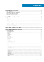
Contents Chapter 1: Working on your computer 5 Safety instructions...5 Turning off your computer - Windows 10...5 Before working inside your computer...6 After working inside your computer 81 Display bezel...89 Display panel...93 Display cable...99 Power-adapter port...103 Camera...105 Contents 3 - Dell Latitude 3400 | Service Manual - Page 4
Palmrest...109 Chapter 5: Troubleshooting...111 Enhanced Pre-Boot System Assessment - ePSA diagnostics 111 Running the ePSA Diagnostics...111 Diagnostics...112 M-BIST...112 L-BIST...112 Diagnostic LED...113 Battery status LED...113 Chapter 6: Getting help...115 Contacting Dell...115 4 Contents - Dell Latitude 3400 | Service Manual - Page 5
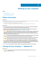
computer, replace all troubleshooting and simple repairs as authorized in your product documentation, or as directed by the online or telephone service and support team. Damage due to servicing that is not authorized by Dell is not covered by your warranty. Read and follow the safety instructions - Dell Latitude 3400 | Service Manual - Page 6
system, see the documentation of your operating system for shut-down instructions. 3. Disconnect your computer and all attached devices from their electrical peripherals, or cables you removed before working on your computer. 3. Replace any media cards, discs, or any other parts that you removed - Dell Latitude 3400 | Service Manual - Page 7
memory into the system. DDR4 needs 20 percent less or just 1.2 volts, compared to DDR3 which requires 1.5 volts of electrical power to operate. DDR4 also supports a new, deep power-down mode that allows the host device to go into standby without needing to refresh its memory. Deep power-down mode is - Dell Latitude 3400 | Service Manual - Page 8
, the LCD does not turn on. Troubleshoot for possible memory failure by trying known is imbedded in board and not a replaceable DIMM as shown and referred. USB features like mice, keyboards, external drivers, and printers. Table 1. Full-duplex data transfers and support for new transfer types • - Dell Latitude 3400 | Service Manual - Page 9
3.1 Gen 1 products: • External Desktop USB 3.0/USB 3.1 Gen 1 Hard Drives • Portable USB 3.0/USB 3.1 Gen 1 Hard Drives • USB 3.0/USB 3.1 Gen 1 Drive Docks & Adapters • USB 3.0/USB 3.1 Gen 1 Flash Drives & Readers • USB 3.0/USB 3.1 Gen 1 Solid-state Drives • USB 3.0/USB 3.1 Gen 1 RAIDs • Optical Media - Dell Latitude 3400 | Service Manual - Page 10
neither replaces nor adds to the memory (RAM) installed on your computer. NOTE: Intel Optane memory is supported on computers that meet the following requirements: • 7th Generation or higher Intel Core i3/i5/i7 processor • Windows 10 64-bit version or higher • Intel Rapid Storage Technology driver - Dell Latitude 3400 | Service Manual - Page 11
memory, do not uninstall the driver for Intel Rapid Storage Technology as it will result in a blue screen error. The Intel Rapid Storage Maximum Power Consumption (TDP) Overlay Planes Operating Systems Graphics/ Video API Support Integrated LPDDR3 i3/i5/i7: G T2 (UHD 620) 15 W (included in the CPU - Dell Latitude 3400 | Service Manual - Page 12
Refresh Rate Up to 85 Hz depending on resolution Multiple Display Support On System: eDP (internal), HDMI Via Optional USB Type-C Port: VGA, DisplayPort External Connectors HDMI 1.4b USB Type-C port Nvidia GeForce MX130 equivalent Table 4. Nvidia GeForce MX130 specifications Feature Graphics - Dell Latitude 3400 | Service Manual - Page 13
3 Major components of your system 1. Base cover 2. Power adapter port Major components of your system 13 - Dell Latitude 3400 | Service Manual - Page 14
10. Touchpad assembly 11. Display assembly 12. Hard drive assembly 13. IO board 14. VGA daughterboard 15. System fan 16. Heatsink NOTE: Dell provides a list of components and their part numbers for the original system configuration purchased. These parts are available according to warranty coverages - Dell Latitude 3400 | Service Manual - Page 15
4 Removing and installing components Topics: • Recommended tools Recommended tools The procedures in this document may require the following tools: • Phillips #0 screwdriver • Phillips #1 screwdriver • Plastic scribe-Recommended for field technician Secure Digital Card Removing the Secure Digital - Dell Latitude 3400 | Service Manual - Page 16
Installing the Secure Digital card Steps 1. Slide the secure digital into the slot until it clicks into place. 2. Follow the procedures in After working inside your computer. 16 Removing and installing components - Dell Latitude 3400 | Service Manual - Page 17
Base cover Removing the base cover Prerequisites 1. Follow the procedure in before working inside your computer 2. Remove the SD memory card Steps 1. Loosen the nine captive screws that secure the base cover to the palmrest and keyboard assembly. Removing and installing components 17 - Dell Latitude 3400 | Service Manual - Page 18
2. Pry the base cover and continue to open the right side of the base cover. 18 Removing and installing components - Dell Latitude 3400 | Service Manual - Page 19
3. Lift the right side of the base cover [1], and remove it off the palmrest and keyboard assembly [2]. Removing and installing components 19 - Dell Latitude 3400 | Service Manual - Page 20
Installing the base cover Steps 1. Place the base cover on the palmrest and keyboard assembly [1]. 20 Removing and installing components - Dell Latitude 3400 | Service Manual - Page 21
2. Tighten the nine captive screws that secure the base cover to the palmrest and keyboard assembly. Removing and installing components 21 - Dell Latitude 3400 | Service Manual - Page 22
Replace to pry on or against the battery. • Ensure any screws during the servicing of this product are not lost or misplaced, to prevent accidental puncture or Dell technical support for assistance. See www.dell.com/contactdell. • Always purchase genuine batteries from www.dell.com or authorized Dell - Dell Latitude 3400 | Service Manual - Page 23
Removing the battery Prerequisites 1. Follow the procedure in before working inside your computer 2. Remove the SD memory card 3. Remove the base cover Steps 1. Disconnect the battery cable from the system board. 2. Remove the four (M2x3) screws that secure the battery to the palmrest and keyboard - Dell Latitude 3400 | Service Manual - Page 24
Installing the battery Steps 1. Align the screw holes on the battery with the screw holes on the palmrest and keyboard assembly [1]. 2. Replace the four (M2x3) screws that secure the battery to the palmrest and keyboard assembly [2]. 24 Removing and installing components - Dell Latitude 3400 | Service Manual - Page 25
3. Connect the battery cable to the system board. Removing and installing components 25 - Dell Latitude 3400 | Service Manual - Page 26
Next steps 1. Replace the base cover 2. Replace the SD memory card 3. Follow the procedure in after working inside your computer Hard drive Removing the hard drive assembly Prerequisites 1. Follow the procedure in - Dell Latitude 3400 | Service Manual - Page 27
hard drive assembly Steps 1. Align the screw holes on the hard drive assembly with the screw holes on the palm rest and keyboard assembly [1]. 2. Replace the four (M2x4.5) screws that secure the hard drive assembly to the palm rest and keyboard assembly [2]. Removing and installing components 27 - Dell Latitude 3400 | Service Manual - Page 28
3. Adhere the tape that secures the hard drive cable to the system board [1]. 4. Connect the hard drive cable to the system board [2]. 28 Removing and installing components - Dell Latitude 3400 | Service Manual - Page 29
Next steps 1. Replace the battery cable. 2. Replace the base cover 3. Replace the SD memory card 4. Follow the procedure in after working inside your computer IO board Removing the IO board Prerequisites 1. Follow the procedure in before - Dell Latitude 3400 | Service Manual - Page 30
Installing the IO board Steps 1. Using the alignment posts, place the I/O board on the palm rest and keyboard assembly [1]. 2. Replace the two (M2x3) screws that secure the I/O board to the palm rest and keyboard assembly [2]. 30 Removing and installing components - Dell Latitude 3400 | Service Manual - Page 31
3. Adhere the I/O board cable to the palm rest and keyboard assembly [1]. 4. Connect the I/O board cable to the system board and close the latch to secure the cable [2]. Removing and installing components 31 - Dell Latitude 3400 | Service Manual - Page 32
the hard drive assembly. NOTE: Required for systems with 42 Whr battery 2. Replace the battery. 3. Replace the base cover. 4. Replace the SD memory card. 5. Follow the procedure in after working inside your computer. Touchpad Removing the touchpad assembly Prerequisites NOTE: For information only - Dell Latitude 3400 | Service Manual - Page 33
5. Remove the four (M2x2) screws that secure the touchpad to the palmrest and keyboard assembly [1]. 6. Lift the touchpad off the palmrest and keyboard assembly [2]. Removing and installing components 33 - Dell Latitude 3400 | Service Manual - Page 34
that the touch pad is aligned with the guides available on the palm-rest and keyboard assembly, and the gap on either sides of the touch pad is equal. Steps 1. Place the touch pad into the slot on the palmrest and keyboard assembly [1]. 2. Replace the four (M2x2) screws that secure the touch - Dell Latitude 3400 | Service Manual - Page 35
5. Place the touch pad bracket into the slot on the palmrest and keyboard assembly [1]. 6. Replace the three screws (M2x2) that secure the touch pad bracket to the palmrest and keyboard assembly [2], and adhere the tape that secures the bracket to - Dell Latitude 3400 | Service Manual - Page 36
Next steps 1. Replace the battery 2. Replace the base cover 3. Replace the SD memory card 4. Follow the procedure in after working inside your computer Memory modules Removing the memory module Prerequisites 1. Follow the procedure in before - Dell Latitude 3400 | Service Manual - Page 37
NOTE: If you do not hear the click, remove the memory module and reinstall it. Next steps 1. Replace the battery cable. 2. Replace the base cover 3. Replace the SD memory card 4. Follow the procedure in after working inside your computer SIM Card Removing the SIM card Prerequisites 1. Follow the - Dell Latitude 3400 | Service Manual - Page 38
Installing the SIM card Steps 1. Open the latch that covers the SIM card slot to release it from the system [1]. 2. Insert a needle in the slot and push it to eject the SIM card tray [2]. 3. Pull the SIM card try and place the SIM card on the SIM cad tray [3] and [4]. 4. Slide the SIM card tray into - Dell Latitude 3400 | Service Manual - Page 39
5. Follow the procedures in After working inside your computer. WLAN card Removing the WLAN card Prerequisites 1. Follow the procedure in before working inside your computer 2. Remove the SD memory card 3. Remove the base cover 4. Disconnect the battery cable. Steps 1. Remove the single (M2x3) screw - Dell Latitude 3400 | Service Manual - Page 40
[1]. 2. Connect the WLAN cables to the connectors on the WLAN card [2]. 3. Place the WLAN card bracket to secure the WLAN cables to the WLAN card [3]. 4. Replace the single (M2x3) screw to secure the WLAN bracket to the WLAN card [4]. 40 Removing and installing components - Dell Latitude 3400 | Service Manual - Page 41
Next steps 1. Disconnect the battery cable. 2. Replace the base cover. 3. Replace the SD memory card. 4. Follow the procedure in after working inside your computer. WWAN card Removing the WWAN card Prerequisites 1. Follow the procedure in before - Dell Latitude 3400 | Service Manual - Page 42
[1]. 2. Connect the WWAN cables to the connectors on the WWAN card [2]. 3. Place the WWAN card bracket to secure the WWAN cables to the WWAN card [3]. 4. Replace the single (M2x3) screw to secure the WWAN bracket to the WWAN card [4]. 42 Removing and installing components - Dell Latitude 3400 | Service Manual - Page 43
Next steps 1. Connect the battery cable. 2. Replace the base cover. 3. Replace the SIM card 4. Replace the SD memory card. 5. Follow the procedure in after working inside your computer. WWAN daughterboard Removing the WWAN daughterboard Prerequisites 1. Follow the procedure in before - Dell Latitude 3400 | Service Manual - Page 44
Steps 1. Open the latch and disconnect the WWAN daughterboard cable from the WWAN daughterboard. 44 Removing and installing components - Dell Latitude 3400 | Service Manual - Page 45
card, do not place any cables under it. Steps 1. Using the alignment posts, place the WWAN daughterboard on the palm rest and keyboard assembly [1] 2. Replace the two (M2x3) screws that secure the WWAN daughterboard to the palm rest and keyboard assembly [2]. Removing and installing components 45 - Dell Latitude 3400 | Service Manual - Page 46
3. Connect the WWAN daughterboard cable to the connector on the WWAN daughterboard and close the latch to secure the cable [1]. 46 Removing and installing components - Dell Latitude 3400 | Service Manual - Page 47
the WWAN card 2. Connect the battery cable. 3. Replace the base cover. 4. Replace the SIM card 5. Replace the SD memory card. 6. Follow the procedure in after working inside your computer. Solid-state drive/Intel Optane memory module Removing the M.2 2280 Solid-state - Dell Latitude 3400 | Service Manual - Page 48
4. Remove the single (M2x2) screw that secures the solid-state drive/Intel Optane card to the palmrest and keyboard assembly [1]. 5. Slide and lift the solid-state drive/Intel Optane card off the palmrest and keyboard assembly [2]. 48 Removing and installing components - Dell Latitude 3400 | Service Manual - Page 49
Optional Steps 1. Slide and insert the tab solid-state drive/Intel Optane card into the solid-state drive/Intel Optane card slot [1]. 2. Replace the single (M2x2) screw that secures the solid-state drive/Intel Optane card to the palmrest and keyboard assembly [2]. Removing and installing components - Dell Latitude 3400 | Service Manual - Page 50
50 Removing and installing components - Dell Latitude 3400 | Service Manual - Page 51
the single (M2x3) screw that secures the thermal plate to the palmrest and keyboard assembly [3]. Next steps 1. Replace the battery cable. 2. Replace the base cover 3. Replace the SD memory card 4. Follow the procedure in after working inside your computer Removing the M.2 Solid-state drive bracket - Dell Latitude 3400 | Service Manual - Page 52
Installing the Solid-state drive bracket Steps 1. Align and replace the solid-state drive bracket on the palmrest and keyboard assembly [1]. 2. Replace the single (M2x3) screw that secures the solid-state drive bracket to the palmrest and keyboard assembly [2]. 52 Removing and installing - Dell Latitude 3400 | Service Manual - Page 53
Next steps 1. Replace the battery cable. 2. Replace the base cover 3. Replace the SD memory card 4. Follow the procedure in after working inside your computer Removing the M.2 2230 Solid-state drive Prerequisites 1. Follow the procedure in before - Dell Latitude 3400 | Service Manual - Page 54
4. Remove the single (M2x2) screw that secures the solid-state drive to the solid-state drive bracket [1]. 5. Slide and remove the solid-state drive off the solid-state drive slot [2]. 54 Removing and installing components - Dell Latitude 3400 | Service Manual - Page 55
Installing the M.2 2230 Solid-state drive Steps 1. Insert the solid-state drive into the solid-state drive slot on the system board [1]. 2. Replace the single (M2x3) screw that secures the solid-state drive to the solid-state drive bracket [2]. Removing and installing components 55 - Dell Latitude 3400 | Service Manual - Page 56
3. Align and replace the thermal plate on the solid-state drive [1,2]. 4. Replace the single (M2x3) screw that secures the thermal plate to the palmrest and keyboard assembly [3]. 56 Removing and installing components - Dell Latitude 3400 | Service Manual - Page 57
Next steps 1. Replace the battery cable. 2. Replace the base cover 3. Replace the SD memory card 4. Follow the procedure in after working system board [1]. 2. Unroute and remove the speaker cable from the routing guides on palm rest and keyboard assembly [2]. Removing and installing components 57 - Dell Latitude 3400 | Service Manual - Page 58
3. Lift the speakers, along with the cable, off the palm rest and keyboard assembly. 58 Removing and installing components - Dell Latitude 3400 | Service Manual - Page 59
Installing the speakers About this task NOTE: If the rubber grommets are pushed out when removing the speakers, push them back in before replacing the speakers. Steps 1. Using the alignment posts and rubber grommets, place the speakers in the slots on the palm rest and keyboard assembly. Removing - Dell Latitude 3400 | Service Manual - Page 60
2. Route the speaker cable through the routing guides on the palm rest and keyboard assembly [1]. 3. Connect the speaker cable to the system board [2]. 60 Removing and installing components - Dell Latitude 3400 | Service Manual - Page 61
Next steps 1. Replace the battery cable. 2. Replace the base cover 3. Replace the SD memory card 4. Follow the procedure in after working inside your computer System fan Removing the system fan Prerequisites 1. Follow the procedure in before - Dell Latitude 3400 | Service Manual - Page 62
2. Unroute the VGA board cable and the display cable from the routing guides on the fan [1]. 3. Disconnect the fan cable from the system board [2]. 4. Remove the two (M2x3) screws that secure the fan to the palmrest and keyboard board assembly [1]. 62 Removing and installing components - Dell Latitude 3400 | Service Manual - Page 63
[2]. Installing the system fan Steps 1. Align the screw holes on the fan with the screw holes on to the palm rest and keyboard board assembly [1]. 2. Replace the two (M2x3) screws that secure the fan to the palm rest and keyboard board assembly [2]. Removing and installing components 63 - Dell Latitude 3400 | Service Manual - Page 64
3. Connect the fan cable to the system board [1]. 4. Route the VGA board cable and the display cable through the routing guides on the fan [2]. 64 Removing and installing components - Dell Latitude 3400 | Service Manual - Page 65
5. Connect the VGA board cable [1], and the display cable [2, 3] to the system board. Next steps 1. Replace the battery. 2. Replace the base cover. 3. Replace the SD memory card. 4. Follow the procedure in after working inside your computer. Heat sink Removing the heatsink-UMA Prerequisites 1. - Dell Latitude 3400 | Service Manual - Page 66
Installing the heatsink-UMA Steps 1. Place the heatsink on the system board and align the screw holes on the heatsink with the screw holes on the system board [1]. 2. In sequential order (as indicated on the heatsink), tighten the four captive screws that secure the heatsink to the system board [2]. - Dell Latitude 3400 | Service Manual - Page 67
Next steps 1. Replace the battery 2. Replace the base cover 3. Replace the SD memory card 4. Follow the procedure in after working inside your computer Removing the heatsink-discrete Prerequisites 1. Follow the procedure in before working inside - Dell Latitude 3400 | Service Manual - Page 68
Installing the heatsink-discrete Steps 1. Place the heatsink on the system board and align the screw holes on the heatsink with the screw holes on the system board [1]. 2. In sequential order (as indicated on the heatsink), tighten the seven captive screws that secure the heatsink to the system - Dell Latitude 3400 | Service Manual - Page 69
Next steps 1. Replace the battery 2. Replace the base cover 3. Replace the SD memory card 4. Follow the procedure in after working inside VGA daughterboard cable from the system board [1]. 2. Unroute the VGA board cable from the routing guides on the fan [2]. Removing and installing components 69 - Dell Latitude 3400 | Service Manual - Page 70
3. Remove the two (M2x3) screws that secure the VGA daughterboard to the palmrest and keyboard assembly [1]. 4. Lift the VGA daughterboard away from the system [2]. 70 Removing and installing components - Dell Latitude 3400 | Service Manual - Page 71
1. Place the VGA daughterboard and align the screw holes on the VGA daughterboard with the screw holes on the palmrest and keyboard assembly [1]. 2. Replace the two (M2x3) screws that secure the VGA daughterboard on the palmrest and keyboard assembly [2]. 3. Route the VGA board cable through the - Dell Latitude 3400 | Service Manual - Page 72
Next steps 1. Replace the battery 2. Replace the base cover 3. Replace the SD memory card 4. Follow the procedure in after working inside your computer Power-button board Removing the power button board with optional fingerprint reader - Dell Latitude 3400 | Service Manual - Page 73
4. Remove the single (M2x3) screw that secures the power button board to the palmrest and keyboard assembly [1]. 5. Lift the power button board, along with the cable off the palmrest and keyboard assembly [2]. Removing and installing components 73 - Dell Latitude 3400 | Service Manual - Page 74
power button board with optional fingerprint reader Steps 1. Place the power-button board into the slot on the palmrest and keyboard assembly [1]. 2. Replace the single (M2x3) screw that secures the power button board to the palmrest and keyboard assembly [2]. 3. Affix the conductive tape to the - Dell Latitude 3400 | Service Manual - Page 75
Next steps 1. Replace the display assembly. 2. Replace the system fan. 3. Replace the battery. 4. Replace the base cover. 5. Replace the SD memory card. 6. Follow the procedure in after working inside your computer. System board Removing the system board Prerequisites 1. Follow the procedure in - Dell Latitude 3400 | Service Manual - Page 76
a. Power button board [1]. b. Fingerprint reader (optional) [2]. c. IO board [3]. d. Touchpad [4]. e. Keyboard [5]. 2. Disconnect the following cables from the system board: a. DC-in [1, 2]. b. Speaker [3]. 76 Removing and installing components - Dell Latitude 3400 | Service Manual - Page 77
3. Remove the three (M2x3) screws and two (M2x2) screws that secure the system board to the palmrest and keyboard assembly [1]. 4. Lift the system board off the palm-rest and keyboard assembly [2]. Removing and installing components 77 - Dell Latitude 3400 | Service Manual - Page 78
Installing the system board Steps 1. Align the screw hole on the system board with the screw hole on the palmrest and keyboard assembly [1]. 2. Replace the three (M2x3) screws and two (M2x2) screws that secure the system board to the palmrest and keyboard assembly [2]. 78 Removing and installing - Dell Latitude 3400 | Service Manual - Page 79
3. Connect the following cables to the system board: a. DC-in [1, 2]. b. Speaker [3]. Removing and installing components 79 - Dell Latitude 3400 | Service Manual - Page 80
4. Connect the following cables to the system board: a. Power button board [1]. b. Fingerprint reader (optional) [2]. c. IO board [3]. d. Touchpad [4]. e. Keyboard [5]. 80 Removing and installing components - Dell Latitude 3400 | Service Manual - Page 81
Next steps 1. Replace the display assembly. 2. Replace the heatsink. 3. Replace the system fan. 4. Replace the SSD. 5. Replace the Memory. 6. Replace the WLAN. 7. Replace the battery. 8. Replace the base cover. 9. Replace the SD memory card. 10. Follow the procedure in after working inside your - Dell Latitude 3400 | Service Manual - Page 82
3. Unroute the display cable from the routing guides on the palmrest and keyboard assembly [1]. 4. Remove the six (M2.5x5) screws that secure the left and right hinges to the system board, and palmrest and keyboard assembly [2]. 82 Removing and installing components - Dell Latitude 3400 | Service Manual - Page 83
5. Lift the palmrest and keyboard assembly at an angle [1]. 6. Continue to lift the palmrest and keyboard assembly until it separates from the hinges [2]. Removing and installing components 83 - Dell Latitude 3400 | Service Manual - Page 84
7. Slide and remove the palmrest and keyboard assembly off the display assembly. 84 Removing and installing components - Dell Latitude 3400 | Service Manual - Page 85
you are left with display assembly. Installing the display assembly About this task NOTE: Ensure that the hinges are opened to the maximum before replacing the display assembly on the palmrest and keyboard assembly. Steps 1. Align and place the palmrest and keyboard assembly under the hinges on the - Dell Latitude 3400 | Service Manual - Page 86
2. Press the hinges down on the system board, and palmrest and keyboard assembly [1]. 3. Seat the palmrest and keyboard assembly on the display assembly [2]. 86 Removing and installing components - Dell Latitude 3400 | Service Manual - Page 87
4. Replace the six (M2.5x5) screws that secure the left and right hinges to the system board, and palmrest and keyboard assembly [1]. 5. Route the display cable through the routing guides on the palmrest and keyboard assembly [2]. Removing and installing components 87 - Dell Latitude 3400 | Service Manual - Page 88
6. Affix the antenna cables to the system board [1]. 7. Connect the display cable to the connector on the system board [2]. 88 Removing and installing components - Dell Latitude 3400 | Service Manual - Page 89
Next steps 1. Replace the WLAN. 2. Replace the battery. 3. Replace the base cover. 4. Replace the SD memory card. 5. Follow the procedure in after working inside your computer. Display bezel Removing the display bezel Prerequisites 1. Follow the procedure in before - Dell Latitude 3400 | Service Manual - Page 90
3. Lift the bezel off the display assembly. 90 Removing and installing components - Dell Latitude 3400 | Service Manual - Page 91
Installing the display bezel Steps 1. Align the display bezel with the display back-cover. Removing and installing components 91 - Dell Latitude 3400 | Service Manual - Page 92
2. Gently snap the display bezel into place. 92 Removing and installing components - Dell Latitude 3400 | Service Manual - Page 93
Next steps 1. Replace the display assembly 2. Replace the WLAN 3. Replace the battery 4. Replace the base cover 5. Replace the SD memory card 6. Follow the procedure in after working inside your computer Display panel Removing the display panel Prerequisites 1. Follow the procedure in before - Dell Latitude 3400 | Service Manual - Page 94
3. Peel the tape that secures the display cable to the back of the display panel [1]. 4. Lift the latch and disconnect the display cable from the display-panel cable connector [2]. 5. Lift the display panel away from the display back-cover [3]. 94 Removing and installing components - Dell Latitude 3400 | Service Manual - Page 95
NOTE: Do not pull and release the Stretch (SR) Tapes from the display panel. There is no need to separate the brackets from the display panel. 6. After performing all the preceding steps, you are left with the display panel. Removing and installing components 95 - Dell Latitude 3400 | Service Manual - Page 96
Installing the display panel Steps 1. Place the display panel on a flat and clean surface. 96 Removing and installing components - Dell Latitude 3400 | Service Manual - Page 97
2. Connect the display cable to the connector at the back of the display panel and close the latch to secure the cable [1]. 3. Adhere the tape that secures the display cable to the back of the display panel [2]. 4. Turn the display panel over and place it on the display back-cover [3]. Removing and - Dell Latitude 3400 | Service Manual - Page 98
5. Align the screw holes on the display panel with the screw holes on the display back-cover [1]. 6. Replace the six (M2x2) and two (M2x3) screws that secure the display panel to the display back-cover [2]. 98 Removing and installing components - Dell Latitude 3400 | Service Manual - Page 99
Next steps 1. Replace the display bezel 2. Replace the display assembly 3. Replace the WLAN 4. Replace the battery 5. Replace the base cover 6. Replace the SD memory card 7. Follow the procedure in after working inside your computer Display cable Removing the display cable Prerequisites 1. Follow - Dell Latitude 3400 | Service Manual - Page 100
Steps 1. Remove the camera cable and the display cable from the routing guides on the display back-cover [1,2]. 2. Peel the adhesive that secures the camera cable [3]. 3. Lift the camera cable and the display cable off the display back-cover. 100 Removing and installing components - Dell Latitude 3400 | Service Manual - Page 101
Installing the display cable Steps 1. Place the display cable and camera cable on the display back-cover. Removing and installing components 101 - Dell Latitude 3400 | Service Manual - Page 102
2. Route the display cable and camera cable through the routing guides on the display back-cover and antenna assembly [1,2]. 3. Affix the adhesive that secures the camera cable [3]. 102 Removing and installing components - Dell Latitude 3400 | Service Manual - Page 103
Replace the display panel 2. Replace the display bezel 3. Replace the display assembly 4. Replace the WLAN 5. Replace the battery 6. Replace the base cover 7. Replace the SD memory card 8. Follow the procedure in after working inside your computer Power-adapter port Removing the power adapter port - Dell Latitude 3400 | Service Manual - Page 104
Installing the power adapter port Steps 1. Place the power adapter port into the slot on the palmrest and keyboard assembly [1]. 2. Replace the single (M2x3) screw that secures the power adapter port to the palmrest and keyboard assembly [2]. 3. Connect the power adapter cable to the system board - Dell Latitude 3400 | Service Manual - Page 105
Next steps 1. Replace the WLAN 2. Replace the battery 3. Replace the base cover 4. Replace the SD memory card 5. Follow the procedure in after working inside your computer Camera Removing the camera Prerequisites 1. Follow the procedure in before working inside - Dell Latitude 3400 | Service Manual - Page 106
Follow the below procedure to remove the camera in systems with the Touch functionality. 4. Peel the tape that secures the camera off the display back-cover [1]. 5. Lift the camera module from the display back-cover [2]. 106 Removing and installing components - Dell Latitude 3400 | Service Manual - Page 107
Installing the camera Steps 1. Connect the camera cable to the camera module [1]. 2. Route the camera cable through the routing channels [2]. 3. Using the alignment post, adhere the camera module on the display back-cover [3]. Removing and installing components 107 - Dell Latitude 3400 | Service Manual - Page 108
Following is the procedure to install the camera in systems with the Touch functionality. 4. Align and replace the camera module on the display back-cover [1]. 5. Adhere the tape that secures the camera off the display back-cover [2]. 108 Removing and installing components - Dell Latitude 3400 | Service Manual - Page 109
Next steps 1. Replace the display panel. 2. Replace the display bezel. 3. Replace the display assembly. 4. Replace the WLAN. 5. Replace the battery. 6. Replace the base cover. 7. Replace the SD memory card. 8. Follow the procedure in after working inside your computer. Palmrest Removing the palmrest - Dell Latitude 3400 | Service Manual - Page 110
the preceding steps, you are left with the palmrest and keyboard assembly. NOTE: The power button board is not included with the service replacement palmrest assembly. Ensure the power button board is replaced onto the service replacement palmrest assembly. 110 Removing and installing components - Dell Latitude 3400 | Service Manual - Page 111
successfully • View error messages that inform you of problems encountered during testing NOTE: Some tests for specific the computer boots, press the F12 key when the Dell logo is displayed. 3. In the boot menu screen, use Up/Down arrow key to select the Diagnostics Dell. or Troubleshooting 111 - Dell Latitude 3400 | Service Manual - Page 112
instruction problem with the system board. board. M-BIST M-BIST is the system board's built-in self-test diagnostics tool that improves the diagnostics accuracy of system board embedded controller (EC) failures. M-BIST can be manually Replace the system board in this case. 112 Troubleshooting - Dell Latitude 3400 | Service Manual - Page 113
. Flash latest BIOS version. If problem persists, replace the system board. Battery status LED Table 7. Battery status LED Power Source LED behavior AC Adapter Solid White AC Adapter Solid White System Power State S0 S4/S5 Battery Charge Level 0-100% < Fully Charged Troubleshooting 113 - Dell Latitude 3400 | Service Manual - Page 114
at an OFF state, expect for a trickle power. The context data is written to hard drive. • S5 (OFF) - The system is in a shutdown state. 114 Troubleshooting - Dell Latitude 3400 | Service Manual - Page 115
. Availability varies by country and product, and some services may not be available in your area. To contact Dell for sales, technical support, or customer service issues: Steps 1. Go to Dell.com/support. 2. Select your support category. 3. Verify your country or region in the Choose a Country
-
 1
1 -
 2
2 -
 3
3 -
 4
4 -
 5
5 -
 6
6 -
 7
7 -
8
-
9
-
10
-
11
-
12
-
13
-
14
-
15
-
16
-
17
-
18
-
19
-
20
-
21
-
22
-
23
-
24
-
25
-
26
-
27
-
28
-
29
-
30
-
31
-
32
-
33
-
34
-
35
-
36
-
37
-
38
-
39
-
40
-
41
-
42
-
43
-
44
-
45
-
46
-
47
-
48
-
49
-
50
-
51
-
52
-
53
-
54
-
55
-
56
-
57
-
58
-
59
-
60
-
61
-
62
-
63
-
64
-
65
-
66
-
67
-
68
-
69
-
70
-
71
-
72
-
73
-
74
-
75
-
76
-
77
-
78
-
79
-
80
-
81
-
82
-
83
-
84
-
85
-
86
-
87
-
88
-
89
-
90
-
91
-
92
-
93
-
94
-
95
-
96
-
97
-
98
-
99
-
100
-
101
-
102
-
103
-
104
-
105
-
106
-
107
-
108
-
109
-
110
-
111
-
112
-
113
-
114
-
115
 |
 |

Dell Latitude 3400
Service Manual
Regulatory Model: P111G
Regulatory Type: P111G001
August 2020
Rev. A01