Dell Latitude 3190 Owners Manual
Dell Latitude 3190 Manual
 |
View all Dell Latitude 3190 manuals
Add to My Manuals
Save this manual to your list of manuals |
Dell Latitude 3190 manual content summary:
- Dell Latitude 3190 | Owners Manual - Page 1
Latitude 3190 Owner's Manual Regulatory Model: P26T Regulatory Type: P26T004 - Dell Latitude 3190 | Owners Manual - Page 2
data and tells you how to avoid the problem. WARNING: A WARNING indicates a potential for property damage, personal injury, or death. © 2018 2019 Dell Inc. or its subsidiaries. All rights reserved. Dell, EMC, and other trademarks are trademarks of Dell Inc. or its subsidiaries. Other trademarks may - Dell Latitude 3190 | Owners Manual - Page 3
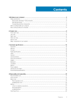
Contents 1 Working on your computer...6 Safety precautions...6 Electrostatic discharge-ESD protection...6 ESD field service kit ...7 Transporting sensitive components...8 Before working inside your computer...8 After working inside your computer...8 2 Chassis view...9 Front open view...9 Left view - Dell Latitude 3190 | Owners Manual - Page 4
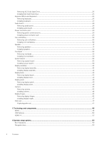
Removing M.2 Solid State Drive...25 Installing M.2 Solid State Drive ...25 Keyboard lattice and Keyboard...26 Removing keyboard...26 Installing keyboard...27 Audio board...28 Removing audio board...28 Installing audio board...28 Power connector port...29 Removing power connector port...29 Installing - Dell Latitude 3190 | Owners Manual - Page 5
options...59 Virtualization support screen options...60 Windows ...61 System and setup password...61 Assigning a system setup password...62 Deleting or changing an existing system setup password 62 7 Software...63 Operating system configurations...63 Downloading drivers...63 8 Troubleshooting - Dell Latitude 3190 | Owners Manual - Page 6
any disassembly instructions. Observe the Dell products with standby power must be unplugged before you open the case This is done through the use of a field service electrostatic discharge (ESD) kit. When connecting a not be obvious, such as intermittent problems or a shortened product life span. - Dell Latitude 3190 | Owners Manual - Page 7
and troubleshoot is casings, away from internal parts that are insulators and often highly charged. • Working Environment - Before deploying the ESD Field Service service technicians use the traditional wired ESD grounding wrist strap and protective anti-static mat at all times when servicing Dell - Dell Latitude 3190 | Owners Manual - Page 8
base, and point your toes out. 2. Tighten stomach muscles. Abdominal muscles support your spine when you lift, offsetting the force of the load. 3. Lift only the battery designed for this particular Dell computer. Do not use batteries designed for other Dell computers. 1. Connect any external devices - Dell Latitude 3190 | Owners Manual - Page 9
Front open view 2 Chassis view 1. Camera 3. Microphone 2. Camera status light 4. Display Chassis view 9 - Dell Latitude 3190 | Owners Manual - Page 10
Left view 1. Power connector port 3. USB 3.1 Gen 1 port Right view 2. HDMI port 4. USB 3.1 Gen 1 port 1. Universal audio jack 2. Battery status light 3. Noble wedge lock slot 10 Chassis view - Dell Latitude 3190 | Owners Manual - Page 11
Palm rest view 1. Power button/power status light 2. keyboard 3. Touchpad Chassis view 11 - Dell Latitude 3190 | Owners Manual - Page 12
Bottom view 1. Air vents 2. Service tag location 3. Speakers 12 Chassis view - Dell Latitude 3190 | Owners Manual - Page 13
Major components of your system 1. Base cover 2. System board Chassis view 13 - Dell Latitude 3190 | Owners Manual - Page 14
metal bracket 6. Palmrest 7. Touchpad 8. Display assembly 9. Audio board 10. Power switch board 11. M.2 Solid State Drive 12. Coin cell NOTE: Dell provides a list of components and their part numbers for the original system configuration purchased. These parts are available according to warranty - Dell Latitude 3190 | Owners Manual - Page 15
by region. For more information regarding the configuration of your computer in: • Windows 10, click or tap Start Topics: • Processor • Memory • Storage • The following GSP processors identified below will be made available to Dell customers. NOTE: Processor numbers are not a measure of performance - Dell Latitude 3190 | Owners Manual - Page 16
UMA Intel UHD Graphics 600 UMA CPU Dependency Graphics memory type Pentium N5000 Integrated Celeron N4100 Integrated Capacity External display support Shared system HDMI 1.4 memory(Upto 8 GB) eDP(Internal) Shared system HDMI 1.4 memory(Upto 8 GB) eDP(Internal) Maximum resolution HDMI - Dell Latitude 3190 | Owners Manual - Page 17
Features Diagonal viewing angle Communications Table 6. Communications Features Network adapter Ports and connectors Table 7. Ports and connectors Features USB Security Audio Video Display Table 8. Display specifications Display specification Type Height (Active area) Width (Active area) Diagonal - Dell Latitude 3190 | Owners Manual - Page 18
NA QWERTY/AZERTY/Kanji Specifications • Horizontal: 1221 • Vertical: 661 • Width: 3.93 inch (100 mm ) • Height: 2.16 inch (55 mm) Supports up to 4 fingers. Gesture support is dependent on operating system. Specifications 42 WHr,3 Cell, Li-ion/Polymer, ExpressCharge Capable Battery • Length: 184 mm - Dell Latitude 3190 | Owners Manual - Page 19
Features Temperature range: Operating Temperature range: Storage Coin-cell battery Specifications • Charge: 0 °C to 35 °C (32 °F to 95 °F) • Discharge: - 40 °C to 65 °C (- 40 °F to 149 °F) -40 °C to 65 °C (-4 °F to 149 °F) ML1220 Power adapter Table 12. Power adapter specifications Features Type - Dell Latitude 3190 | Owners Manual - Page 20
Relative humidity (maximum) Operating Storage Specifications 10 % to 90 % (non condensing) 5 % to 95 % (non condensing) Altitude (maximum) Operating Non-operating Specifications 0 m to 3048 m (0 ft to 10,000 ft) 0 m to 10,668 m (0 ft to 35,000 ft) Airborne G1 as defined by ISA-71.04-1985 - Dell Latitude 3190 | Owners Manual - Page 21
4 Disassembly and reassembly Recommended tools The procedures in this document require the following tools: • Phillips #0 screwdriver • Phillips #1 screwdriver • Plastic scribe NOTE: The #0 screw driver is for screws 0-1 and the #1 screw driver is for screws 2-4. Screw size list Table 14. Screw - Dell Latitude 3190 | Owners Manual - Page 22
b) Pry the base cover from the recesses at the top edges and continue throughout the system [2]. NOTE: Use a plastic scribe to pry the base cover from the recesses at the top edges. 3. Lift the base cover away from the computer. 22 Disassembly and reassembly - Dell Latitude 3190 | Owners Manual - Page 23
to pry on or against the battery. • Ensure any screws during the servicing of this product are not lost or misplaced, to prevent accidental puncture or damage Dell technical support for assistance. See www.dell.com/contactdell. • Always purchase genuine batteries from www.dell.com or authorized Dell - Dell Latitude 3190 | Owners Manual - Page 24
e) Lift the battery from the computer. Installing battery 1. Insert the battery into the slot on the computer. 24 Disassembly and reassembly - Dell Latitude 3190 | Owners Manual - Page 25
2. Affix the adhesive tapes to secure the battery to the system. 3. Connect the battery cable to the connector on the battery. 4. Replace the three M2x3 screws to secure the battery to the computer. 5. Install the: a) base cover 6. Follow the procedure in After working inside your computer. Solid - Dell Latitude 3190 | Owners Manual - Page 26
2. Align the screw hole on the SSD card with the screw hole on the system board. 3. Replace the M2x3 screw that secures the SSD card to the system board. 4. Install the: a) battery b) base cover 5. Follow the procedure in After working inside your computer. Keyboard lattice and Keyboard Removing - Dell Latitude 3190 | Owners Manual - Page 27
Installing keyboard NOTE: Insert the keyboard connector through the gap in the palm rest. NOTE: When installing the keyboard of Latitude 3190 the keyboard FPC must be inserted through the gap carefully at the top side of the palm rest before securing the keyboard onto the system. - Dell Latitude 3190 | Owners Manual - Page 28
a) battery b) base cover 4. Follow the procedure in After working inside your computer. Audio board Removing audio board 1. Follow the procedure in Before working inside your computer. 2. Remove the: a) base cover b) battery 3. To remove the audio board: a) Lift the latch and disconnect the audio - Dell Latitude 3190 | Owners Manual - Page 29
b) base cover 5. Follow the procedure in After working inside your computer. Power connector port Removing power connector port 1. Follow the procedure in Before working inside your computer. 2. Remove the: a) base cover b) battery 3. To remove the power connector port: a) Disconnect the power - Dell Latitude 3190 | Owners Manual - Page 30
5. Follow the procedure in After working inside your computer. Coin-cell battery Removing coin cell battery 1. Follow the procedure in Before working inside your computer. 2. Remove the: a) base cover b) battery 3. To remove the coin cell battery: a) Disconnect the coin cell battery cable from the - Dell Latitude 3190 | Owners Manual - Page 31
Speaker Removing speakers 1. Follow the procedure in Before working inside your computer. 2. Remove the: a) base cover b) battery 3. To remove the speaker: NOTE: When removing the speaker, the audio daughter board FFC must be disconnected from the system board and then peeled back from the palm rest - Dell Latitude 3190 | Owners Manual - Page 32
Installing speakers 1. Place the speakers into the slots on the computer. 2. Route the speaker cable through the retention clips through routing channel. 3. Affix the adhesive tape to secure the speaker cable on the computer. 4. Connect the speaker cable to the connector on the system board. 5. - Dell Latitude 3190 | Owners Manual - Page 33
4. To remove touchpad metal bracket: a) Remove the 5 M2X2 screws and one M2x3 screw that secure the metal bracket to the system. b) Lift the metal bracket away from the system [3] Disassembly and reassembly 33 - Dell Latitude 3190 | Owners Manual - Page 34
5. Remove the touchpad from the computer. Installing the touchpad 1. Place the touchpad into the slot on the system. 2. Align and place touchpad bracket over the plastic hold down and replace the five M2X2 screws and one M2x3 to secure it to the system. 34 Disassembly and reassembly - Dell Latitude 3190 | Owners Manual - Page 35
that secure the thermal plate to the system board do not have to be removed to remove the system board from the system NOTE: The latitude 3190 does not have a heat sink and fan assembly. However, the CPU is covered by a thermal plate and aluminum shielding which should not be disassembled from - Dell Latitude 3190 | Owners Manual - Page 36
4. To remove metal bracket on the system board: a) Remove the two M2x3 screws that secure the IO bracket to the system board [1]. b) Lift the IO bracket from the system board [2]. 36 Disassembly and reassembly - Dell Latitude 3190 | Owners Manual - Page 37
5. To remove the metal bracket (WLAN and display cable): a) Remove the M2x3 screw and lift the metal bracket that secures the WLAN card on the system board [1, 2] b) Disconnect the WLAN cables [3]. c) Remove the two M2.0 x 3.0 screws and lift the metal bracket that secures the display cable on the - Dell Latitude 3190 | Owners Manual - Page 38
6. To remove the system board: a) Remove the five M2x3 screws that secure the system board on the palm rest assembly [1]. b) Lift the system board off the palm- rest assembly [2]. 38 Disassembly and reassembly - Dell Latitude 3190 | Owners Manual - Page 39
Installing system board 1. Align the system board with the screw holders on the palm rest assembly. 2. Replace the five M2x3 screws to secure the system board to the palm rest assembly. 3. Connect the display cable to the connector on the system board. 4. Place the metal bracket over the connector, - Dell Latitude 3190 | Owners Manual - Page 40
Display assembly Removing display assembly 1. Follow the procedure in Before working inside your computer. 2. Remove the: a) base cover b) battery 3. To remove cables: a) Remove the M2x3 screw [1] and lift the metal bracket that secures the WLAN card on the system board [2]. b) Disconnect the WLAN - Dell Latitude 3190 | Owners Manual - Page 41
5. To remove the display assembly: a) Remove the five M2.5x5 screws that secure the display assembly to the computer [1]. b) Lift the display assembly from the computer [2]. Disassembly and reassembly 41 - Dell Latitude 3190 | Owners Manual - Page 42
bezel Removing display bezel 1. Follow the procedure in Before working inside your computer. 2. Remove the: NOTE: The display bezel of Latitude 3190 is a disposable service part that should be replaced with a new display bezel anytime it is removed from the system. This also applies to removal of - Dell Latitude 3190 | Owners Manual - Page 43
Installing display bezel 1. Place the display bezel on the display assembly. 2. Starting from the top corner, press on the display bezel and work around the entire bezel until it clicks on to the display assembly. 3. Replace the four M2.5X3.5 screws to secure the display bezel to the display - Dell Latitude 3190 | Owners Manual - Page 44
4. To remove display panel: a) Peel off the adhesive tape [1]. b) Disconnect the display cable from the connector on the display panel [2]. ' Installing display panel 1. Connect the display cable to the connector, and affix the tape. 44 Disassembly and reassembly - Dell Latitude 3190 | Owners Manual - Page 45
replacing the display cable onto the display back- cover of the Latitude 3190, on-site technicians must first disconnect the cable from the camera note that the display hinges, display cable, and camera are also separate service parts that can be individually replaced Remove the: a) base cover b) - Dell Latitude 3190 | Owners Manual - Page 46
When replacing the display cable onto the display back- cover of the Latitude 3190, on-site technicians must first disconnect the cable from the camera that the display hinges, display cable, and camera are also separate service parts that can be individually replaced Remove the: a) base cover b) - Dell Latitude 3190 | Owners Manual - Page 47
Installing display hinges 1. Place the display hinges on the display back cover. 2. Replace the four M2.5x2.5 screws to secure the display hinges to the display back cover. . 3. Install the: a) display panel b) display bezel c) display assembly d) battery e) base cover 4. Follow the procedure in - Dell Latitude 3190 | Owners Manual - Page 48
NOTE: The component you are left with is the palm rest. 3. Install the following components on the new palm rest: a) display assembly b) speaker c) coin cell battery d) power connector e) audio f) keyboard g) system board h) SSD card i) battery j) base cover 4. Follow the procedure in After working - Dell Latitude 3190 | Owners Manual - Page 49
memory into the system. DDR4 needs 20 percent less or just 1.2 volts, compared to DDR3 which requires 1.5 volts of electrical power to operate. DDR4 also supports a new, deep power-down mode that allows the host device to go into standby without needing to refresh its memory. Deep power-down mode is - Dell Latitude 3190 | Owners Manual - Page 50
failure code. If all memory fails, the LCD does not turn on. Troubleshoot for possible memory failure by trying known good memory modules in the memory connectors • New power management features • Full-duplex data transfers and support for new transfer types • Backward USB 2.0 compatibility • New - Dell Latitude 3190 | Owners Manual - Page 51
USB 3.0/USB 3.1 Gen 1 achieves the much higher performance by the technical changes below: • An additional physical bus that is added in parallel with the existing USB 2.0 bus (refer to the picture below). • USB 2.0 previously had four wires (power, ground, and a pair for differential data); USB - Dell Latitude 3190 | Owners Manual - Page 52
(DTV). The intended applications for HDMI TVs, and DVD players. The primary advantage is cable reduction and content protection provisions. HDMI supports standard, enhanced, or high-definition video, plus multichannel digital audio on a single cable. NOTE: The HDMI 1.4 will provide 5.1 channel audio - Dell Latitude 3190 | Owners Manual - Page 53
screen options • POST behavior screen options • Virtualization support screen options • Wireless screen options • Maintenance screen options • System logs screen options • SupportAssist system resolution • Updating the BIOS in Windows • System and setup password Boot Sequence Boot sequence - Dell Latitude 3190 | Owners Manual - Page 54
down or restart your computer and try again. NOTE: After the Dell logo appears, you can also press F12 and then select BIOS setup Version, Service Tag, Asset Tag, Ownership Tag, Ownership Date, Manufacture Date, Express Service Code, Windows Boot Manager ( Default) • Boot List Option 54 System - Dell Latitude 3190 | Owners Manual - Page 55
and available for OS. If USB port is disabled, the OS cannot see any device attached to this port. The options are: • Enable Boot Support-enabled by default • Enable External USB Port-enabled by default NOTE: USB keyboard and mouse always work in the BIOS setup irrespective of these settings. - Dell Latitude 3190 | Owners Manual - Page 56
Security screen options Option Admin Password Description Allows you to set, change, or delete the administrator (admin) password. NOTE: You must set the admin password before you set the system or hard drive password. Deleting the admin password automatically deletes the system password and the - Dell Latitude 3190 | Owners Manual - Page 57
options will permanently activate or disable the feature and no further changes will be allowed. CPU XD Support Allows you to enable the Execute Disable mode of the processor. Enable CPU XD Support-enabled by default Admin Setup Lockout Allows you to prevent users from entering Setup when an - Dell Latitude 3190 | Owners Manual - Page 58
AC power adapter is removed during Standby, the system setup removes power from all the USB ports to conserve battery power. • Enable USB Wake Support Default setting: The option is disabled. Allows you to enable or disable the feature that powers on the computer from the Off state when triggered - Dell Latitude 3190 | Owners Manual - Page 59
options are: • Adaptive-enabled by default • Standard-Fully charges your battery at a standard rate. • ExpressCharge-The battery charges over a shorter time using Dell's fast charging technology This option is enabled by default. • Primarily AC use • Custom If Custom Charge is selected, you can also - Dell Latitude 3190 | Owners Manual - Page 60
Virtualization support screen options Option Virtualization VT for Direct I/O Description options are enabled by default. Maintenance screen options Option Service Tag Asset Tag BIOS Downgrade Data Wipe BIOS Recovery Description Displays the Service Tag of your computer. Allows you to create a - Dell Latitude 3190 | Owners Manual - Page 61
in Windows It is recommended to update your BIOS (System Setup), when you replace the system board or if an update is available. For laptops, 2. Go to Dell.com/support. • Enter the Service Tag or Express Service Code and click Submit. • Click Detect Product and follow the instructions on screen. - Dell Latitude 3190 | Owners Manual - Page 62
assign the system password: • A password can have up to 32 characters. • The password can contain the numbers 0 through 9. • Only lower case letters are valid, upper case letters are not allowed. • Only the following special characters are allowed: space 3. Type the system password that you entered - Dell Latitude 3190 | Owners Manual - Page 63
This topic lists the operating system supported by Latitude 3190. Table 17. Operating systems Features Microsoft Specifications Windows 10 Pro 64 bit RS4 Downloading drivers 1. Turn on the notebook. 2. Go to Dell.com/support. 3. Click Product Support, enter the Service Tag of your notebook, and - Dell Latitude 3190 | Owners Manual - Page 64
Troubleshooting messages that inform you of problems encountered during testing NOTE: Some As the computer boots, press the F12 key when the Dell logo is displayed. 3. In the boot menu screen, NOTE: The Enhanced Pre-boot System Assessment window displays, listing all devices detected in the computer - Dell Latitude 3190 | Owners Manual - Page 65
• Service Tag • Asset Tag • Ownership Tag • Admin Password • System Password • HDD Password • TPM on and Active • Key Databases • System Logs The reset based on your custom BIOS setting selections: • The Boot List • Enable Legacy OROMs • Secure Boot Enable • Allow BIOS Downgrade Troubleshooting 65
-
 1
1 -
 2
2 -
 3
3 -
 4
4 -
 5
5 -
 6
6 -
 7
7 -
8
-
9
-
10
-
11
-
12
-
13
-
14
-
15
-
16
-
17
-
18
-
19
-
20
-
21
-
22
-
23
-
24
-
25
-
26
-
27
-
28
-
29
-
30
-
31
-
32
-
33
-
34
-
35
-
36
-
37
-
38
-
39
-
40
-
41
-
42
-
43
-
44
-
45
-
46
-
47
-
48
-
49
-
50
-
51
-
52
-
53
-
54
-
55
-
56
-
57
-
58
-
59
-
60
-
61
-
62
-
63
-
64
-
65
 |
 |

Latitude 3190
Owner's Manual
Regulatory Model: P26T
Regulatory Type: P26T004