Dell DSS 7500 DSS 7000/DSS 7500 Owners Manual
Dell DSS 7500 Manual
 |
View all Dell DSS 7500 manuals
Add to My Manuals
Save this manual to your list of manuals |
Dell DSS 7500 manual content summary:
- Dell DSS 7500 | DSS 7000/DSS 7500 Owners Manual - Page 1
Dell DSS 7000/DSS 7500 Owner's Manual Regulatory Model: B14S Regulatory Type: B14S001 - Dell DSS 7500 | DSS 7000/DSS 7500 Owners Manual - Page 2
. CAUTION: A CAUTION indicates either potential damage to hardware or loss of data and tells you how to avoid the problem. WARNING: A WARNING indicates a potential for property damage, personal injury, or death. Copyright © 2016 Dell Inc. All rights reserved. This product is protected by U.S. and - Dell DSS 7500 | DSS 7000/DSS 7500 Owners Manual - Page 3
codes for the redundant PSU 14 Documentation matrix...15 2 Performing initial system configuration 16 Setting up your system...16 Installing the rack and the server 16 Installing the rails...16 Installing the cable management arm (CMA 18 Setting up and configuring the iDRAC IP address 20 - Dell DSS 7500 | DSS 7000/DSS 7500 Owners Manual - Page 4
Dell instructions...42 Before working inside your system 42 After working inside your system 42 Recommended tools...43 System cover...43 Removing the system cover 43 Installing the system cover...44 Server sleds...44 Removing the server sled...44 Installing the server sled specific guidelines...59 - Dell DSS 7500 | DSS 7000/DSS 7500 Owners Manual - Page 5
a 2.5-inch hot-swap HDD 74 Installing a 2.5-inch hot-swap HDD 75 Installing fans...79 Removing a system fan...79 Installing a system fan...80 Removing the fan cage...80 Installing the fan cage...81 PSUs...82 Removing a redundant PSU 82 Installing a redundant PSU...83 System battery...84 Replacing - Dell DSS 7500 | DSS 7000/DSS 7500 Owners Manual - Page 6
system fans...107 Troubleshooting system memory 107 Troubleshooting HDDs...108 Troubleshooting expansion cards 109 Troubleshooting processors...110 Troubleshooting server sleds...110 System messages...110 Warning messages...110 Diagnostic messages...111 6 Using system diagnostics 112 Dell - Dell DSS 7500 | DSS 7000/DSS 7500 Owners Manual - Page 7
Disabling a forgotten password 117 8 Technical specifications 118 9 Getting help...124 Contacting Dell...124 Locating your system Service Tag 124 - Dell DSS 7500 | DSS 7000/DSS 7500 Owners Manual - Page 8
The Dell 4U rack server contains the DSS 7000 chassis and up to two DSS 7500 server sleds. Each server sled supports up to two processors based on the Intel Xeon EP E5-2600 v3 family and EP E5-2600 v4 family, up to 12 DIMMs, and up to two boot solid state drives (SSDs). The chassis supports up - Dell DSS 7500 | DSS 7000/DSS 7500 Owners Manual - Page 9
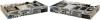
button Power indicator ID indicator Sled B HDD fault status indicator standby, and if any issue exists (for example, a failed fan or HDD). The power button controls the PSU output to the button can be used to locate a particular system within a rack. Press to toggle the system ID on and off. If - Dell DSS 7500 | DSS 7000/DSS 7500 Owners Manual - Page 10
The identification button can be used to locate a particular system within a rack. Press to toggle the system ID on and off. If the system stops indicators 1 2 3 4 5 6 7 8 9 10 11 12 13 14 15 Sled B Sled A 17 Figure 2. Back-panel features and indicators Item 1 Indicator, Button, or - Dell DSS 7500 | DSS 7000/DSS 7500 Owners Manual - Page 11
. Provides persistent on-demand local storage and a custom deployment environment that allows automation of server configuration, scripts and imaging. See the Integrated Dell Remote Access User's Guide at dell.com/idracmanuals. Enables you to connect USB devices to the system. The port is USB - Dell DSS 7500 | DSS 7000/DSS 7500 Owners Manual - Page 12
Power supply units Two redundant power supply units (PSUs) for sled B. NOTE: Features of sled B are for dual-node systems only. NOTE: A dummy sled will be installed over sled B compartment and two dummy PSUs over the PSU slots for sled B for the single-node system. HDD indicator codes Figure - Dell DSS 7500 | DSS 7000/DSS 7500 Owners Manual - Page 13
Figure 4. 3.5-inch HDD indicators 1 HDD activity indicator 3 HDD Drive-status indicator pattern (RAID only) Blinks green two times per second Off Solid orange Steady green NIC indicator codes 2 HDD status indicator Condition Identifying drive or preparing for removal. Normal operation Drive - Dell DSS 7500 | DSS 7000/DSS 7500 Owners Manual - Page 14
Network data Dell Lifecycle Controller User's Guide at dell.com/idracmanuals. When hot-adding a PSU, the PSU handle flashes green five times at 4 Hz rate and turns off. This indicates that there is a PSU mismatch with respect to efficiency, feature set, health status, and supported voltage. Replace - Dell DSS 7500 | DSS 7000/DSS 7500 Owners Manual - Page 15
the rack and the server Configure and log in to iDRAC, set up managed and Integrated Dell Remote Access Controller User's management system, know the iDRAC features and Guide at dell.com/idracmanuals troubleshoot using iDRAC Know about the RACADM subcommands and supported RACADM interfaces - Dell DSS 7500 | DSS 7000/DSS 7500 Owners Manual - Page 16
set up and configure the system iDRAC IP address. Setting up your system 1. Unpack the server. 2. Install the rack. 3. Install the server into the rack. 4. Install the hard disk drives into the chassis. 5. Connect the peripherals to the system. 6. Connect the system to its electrical outlet. 7. Turn - Dell DSS 7500 | DSS 7000/DSS 7500 Owners Manual - Page 17
member back 2. Install the inner member onto the chassis and secure it with the screw. NOTE: Pay attention to the installation direction. Figure 8. Installing the inner member onto the chassis 3. Secure the outer member and bracket into the rack with the screws for both the left and right - Dell DSS 7500 | DSS 7000/DSS 7500 Owners Manual - Page 18
into the intermediate member. The tab must be pressed when pushing the chassis in. c. Secure the inner member with the screw. Figure 10. Installing the chassis into the rack Installing the cable management arm (CMA) 1. Switch the left and right sides of the CMA by pressing the PUSH button and - Dell DSS 7500 | DSS 7000/DSS 7500 Owners Manual - Page 19
2 1 Figure 11. Switching the left and right sides of the CMA 2. The loop strap must be tied to the CMA crossbar. NOTE: The loop strap can be removed - Dell DSS 7500 | DSS 7000/DSS 7500 Owners Manual - Page 20
button on the CMA plug-in part to draw it out. 2 1 Setting up and configuring the iDRAC IP address You can set up the Integrated Dell Remote Access Controller (iDRAC) IP address by using one of the following interfaces: 20 - Dell DSS 7500 | DSS 7000/DSS 7500 Owners Manual - Page 21
Command Line Interface Reference Guide and the Integrated Dell Remote Access Controller User's Guide. • Remote Services that includes Web Services Management (WS-Man). For more information about the Remote Services, see the Lifecycle Controller Remote Services Quick Start Guide. For more information - Dell DSS 7500 | DSS 7000/DSS 7500 Owners Manual - Page 22
configure the supported Web browsers. For more information about configuring iDRAC for remote accessibility, see the Integrated Dell Remote Access Controller User's Guide at dell.com/idracmanuals. You can also remotely monitor and manage the server by using the Dell OpenManage Server Administrator - Dell DSS 7500 | DSS 7000/DSS 7500 Owners Manual - Page 23
the LSI 9311 card on a Ubuntu1404 system 1. Download the required driver (mpt3sas.ko) to a USB drive from dell.com/support/drivers. 2. When prompted by the Ubuntu installer CD, select Ubuntu Server for installation. 3. On the [!]Configure the C lock screen, press Ctrl + Alt + F1 to access a console - Dell DSS 7500 | DSS 7000/DSS 7500 Owners Manual - Page 24
management applications: • System Setup • Boot Manager • Dell Lifecycle Controller Navigation keys The navigation keys can help you Pressing Esc in the main page exits System BIOS/iDRAC Settings/Device Settings/Service Tag Settings and proceeds with system boot. F1 Displays the System Setup - Dell DSS 7500 | DSS 7000/DSS 7500 Owners Manual - Page 25
Dell Remote Access Controller User's Guide at dell.com/idracmanuals. Enables you to configure device settings. System BIOS page By using the System BIOS page, you can view the BIOS settings and edit specific system model name, BIOS version and Service Tag. Displays information and options related - Dell DSS 7500 | DSS 7000/DSS 7500 Owners Manual - Page 26
and TPM security. It also enables or disables support for the power and NMI buttons on the System Information page to view system properties such as Service Tag, system model, and the BIOS version. the memory settings and enable or disable specific memory functions such as system memory testing and - Dell DSS 7500 | DSS 7000/DSS 7500 Owners Manual - Page 27
supported. If this field is Enabled, memory interleaving is supported if a symmetric memory configuration is installed. If Disabled, the system supports processor settings and perform specific functions such as enabling data rate and 6.4 GT/s. By default, the QPI Speed option is set to Maximum data - Dell DSS 7500 | DSS 7000/DSS 7500 Owners Manual - Page 28
Item Address Translation Service (ATS) is set to Enabled. DCU IP Prefetcher Enables or disables the Data Cache Unit (DCU) IP prefetcher. By default, the DCU IP is set to All. Processor 64-bit Support Specifies if the processors support 64-bit extensions. Processor Core Speed Displays the - Dell DSS 7500 | DSS 7000/DSS 7500 Owners Manual - Page 29
selected device. For Embedded SATA settings in ATA mode, set this field to Auto to enable BIOS support. Set it to OFF to turn off BIOS support. For AHCI mode or RAID mode, BIOS always enables support. Displays the drive model of the selected device. Displays the type of drive attached to the - Dell DSS 7500 | DSS 7000/DSS 7500 Owners Manual - Page 30
Mode Description Enables you to set the boot mode of the system. CAUTION: Switching the boot mode may prevent the system from booting if the operating system is Retry Hard-Disk Failover Boot Option Settings If the operating system supports UEFI, you can set this option to UEFI. Setting this - Dell DSS 7500 | DSS 7000/DSS 7500 Owners Manual - Page 31
utilities of the system. I/OAT DMA Engine Allows you to enable or disable the I/OAT option. Enable only if the hardware and software supports the feature. Embedded Video Controller Allows you to enable or disable the Embedded Video Controller. By default, the embedded video controller is Enabled - Dell DSS 7500 | DSS 7000/DSS 7500 Owners Manual - Page 32
is the field is set to Disabled (the default), the timer will have no effect on the system. Memory Mapped I/O above 4 Allows you to enable support for PCIe devices that require large GB amounts of memory. By default, the option is set to Enabled. Slot Disablement Allows you to enable or - Dell DSS 7500 | DSS 7000/DSS 7500 Owners Manual - Page 33
option is set to Performance Per Watt (DAPC). DAPC is Dell Active Power Controller. NOTE: The following parameters are available only when the select Maximum Performance, Maximum Reliability, or a specific speed. Enables or disables the processor to switch to a minimum performance state when it is - Dell DSS 7500 | DSS 7000/DSS 7500 Owners Manual - Page 34
target higher performance or better power savings. Enables the Monitor/Mwait instructions in the processor. By default, the Monitor/Mwait option is Settings page You can use the System Security page to perform specific functions such as setting the system password, setup password and disabling - Dell DSS 7500 | DSS 7000/DSS 7500 Owners Manual - Page 35
option is set to Last. AC Power Recovery Delay Sets how the system supports staggering of power up after AC power is restored to the system. By ) UEFI variables are accessible in the Operating System per the UEFI specification. When set to Controlled, selected UEFI variables are protected in the - Dell DSS 7500 | DSS 7000/DSS 7500 Owners Manual - Page 36
Settings page You can use the Miscellaneous Settings page to perform specific functions such as updating the asset tag and changing the system ROM from the video controller. Selecting Enabled in the operating system does not support UEFI video output standards. This field is only for UEFI boot mode. - Dell DSS 7500 | DSS 7000/DSS 7500 Owners Manual - Page 37
Dell Lifecycle Controller, see the documentation at dell.com/ idracmanuals. Changing the boot order You may have to change the boot order if you want to boot from a USB key or an optical drive. The instructions Unified Extensible Firmware Interface (UEFI) specifications that overlays the system BIOS. - Dell DSS 7500 | DSS 7000/DSS 7500 Owners Manual - Page 38
UEFI and can only be installed from the BIOS boot mode. NOTE: For more information about supported operating systems, go to dell.com/ossupport. Assigning a system and setup password Prerequisites You can assign a new System Password and Setup Password or change an existing System Password and - Dell DSS 7500 | DSS 7000/DSS 7500 Owners Manual - Page 39
Using your system password to secure your system Prerequisites NOTE: If you have assigned a setup password, the system accepts your setup password as an alternate system password. Steps 1. Turn on or reboot your system. 2. Type your password and press Enter. Next steps When Password Status is Locked - Dell DSS 7500 | DSS 7000/DSS 7500 Owners Manual - Page 40
server's lifecycle. The Lifecycle Controller can be started during the boot sequence and can function independently of the operating system. NOTE: Certain platform configurations may not support using iDRAC, see the iDRAC User's Guide at dell.com/idracmanuals. Entering the iDRAC Settings utility - Dell DSS 7500 | DSS 7000/DSS 7500 Owners Manual - Page 41
2. Under iDRAC Settings → Thermal → User Cooling Options, select between the following options: • Default • Custom NOTE: When the User Option is set to the Default setting, the user option cannot be modified. 3. Click Back → Finish → Yes. 41 - Dell DSS 7500 | DSS 7000/DSS 7500 Owners Manual - Page 42
only perform troubleshooting and simple repairs as authorized in your product documentation, or as directed by the online or telephone service and support team. Damage due to servicing that is not authorized by Dell is not covered by your warranty. Read and follow the safety instructions that came - Dell DSS 7500 | DSS 7000/DSS 7500 Owners Manual - Page 43
only perform troubleshooting and simple repairs as authorized in your product documentation, or as directed by the online or telephone service and support team. Damage due to servicing that is not authorized by Dell is not covered by your warranty. Read and follow the safety instructions that came - Dell DSS 7500 | DSS 7000/DSS 7500 Owners Manual - Page 44
system. Removing the server sled Prerequisites CAUTION: Many repairs may only be done by a certified service technician. You should only perform troubleshooting and simple repairs as authorized in your product documentation, or as directed by the online or telephone service and support team. Damage - Dell DSS 7500 | DSS 7000/DSS 7500 Owners Manual - Page 45
(2) server sled Installing the server sled Prerequisites CAUTION: Many repairs may only be done by a certified service technician. You should only perform troubleshooting and simple repairs as authorized in your product documentation, or as directed by the online or telephone service and support - Dell DSS 7500 | DSS 7000/DSS 7500 Owners Manual - Page 46
and PCIE_G3_X16 are the two different types of risers supported on DSS 7500 systems. You can install an expansion card on the system board only using expansion-card riser module. NOTE: The expansion cards are not hot-swappable. 12 34 Sled B Sled A Figure 14. Expansion card slot allocation 46 - Dell DSS 7500 | DSS 7000/DSS 7500 Owners Manual - Page 47
to servicing that is not authorized by Dell is not covered by your warranty. Read and follow the safety instructions that came with the product. 1. Ensure that you read the Safety instructions. 2. Complete the procedure listed in Before working inside your system. 3. Remove the server sled. Steps - Dell DSS 7500 | DSS 7000/DSS 7500 Owners Manual - Page 48
the server sled Removing an expansion card Prerequisites CAUTION: Many repairs may only be done by a certified service technician. You should only perform troubleshooting and simple repairs as authorized in your product documentation, or as directed by the online or telephone service and support - Dell DSS 7500 | DSS 7000/DSS 7500 Owners Manual - Page 49
1. Ensure that you read the Safety instructions. 2. Complete the procedure listed in Before working inside your system. 3. Remove the expansion-card module Installing the expansion-card riser module Installing an expansion card NOTE: Only supported cards from Dell can be installed in the system. 49 - Dell DSS 7500 | DSS 7000/DSS 7500 Owners Manual - Page 50
only perform troubleshooting and simple repairs as authorized in your product documentation, or as directed by the online or telephone service and support team. Damage due to servicing that is not authorized by Dell is not covered by your warranty. Read and follow the safety instructions that came - Dell DSS 7500 | DSS 7000/DSS 7500 Owners Manual - Page 51
3. Remove the expansion-card riser module. Steps 1. Attach and secure the system's expansion-card bracket to the card with two screws. Figure 17. Attaching the bracket to the CX3pro card 1 bracket 2 3 CX3pro card screw (2) Figure 18. Attaching the bracket to the X520 card 1 bracket 2 3 X520 - Dell DSS 7500 | DSS 7000/DSS 7500 Owners Manual - Page 52
the server sled Installing the supercapacitor Prerequisites CAUTION: Many repairs may only be done by a certified service technician. You should only perform troubleshooting and simple repairs as authorized in your product documentation, or as directed by the online or telephone service and support - Dell DSS 7500 | DSS 7000/DSS 7500 Owners Manual - Page 53
Steps Depending on the type of the supercapacitor, follow the illustrations below to install the supercapacitor. 1 Adaptec AFM700 supercapacitor 3 screw (2) 2 extender cable 1 fastener (2) 3 LSI 49571-15 supercapacitor 2 2 LSI 49571-15 supercapacitor 1 4 extender cable (2) 53 - Dell DSS 7500 | DSS 7000/DSS 7500 Owners Manual - Page 54
the server sled Removing a riser card Prerequisites CAUTION: Many repairs may only be done by a certified service technician. You should only perform troubleshooting and simple repairs as authorized in your product documentation, or as directed by the online or telephone service and support team - Dell DSS 7500 | DSS 7000/DSS 7500 Owners Manual - Page 55
only perform troubleshooting and simple repairs as authorized in your product documentation, or as directed by the online or telephone service and support team. Damage due to servicing that is not authorized by Dell is not covered by your warranty. Read and follow the safety instructions that came - Dell DSS 7500 | DSS 7000/DSS 7500 Owners Manual - Page 56
card Installing an expansion card Removing the server sled Installing the server sled Cooling shroud Removing the cooling shroud Prerequisites CAUTION: Many repairs may only be done by a certified service technician. You should only perform troubleshooting and simple repairs as authorized in your - Dell DSS 7500 | DSS 7000/DSS 7500 Owners Manual - Page 57
only perform troubleshooting and simple repairs as authorized in your product documentation, or as directed by the online or telephone service and support team. Damage due to servicing that is not authorized by Dell is not covered by your warranty. Read and follow the safety instructions that came - Dell DSS 7500 | DSS 7000/DSS 7500 Owners Manual - Page 58
Dual rank or single rank 2 2400, 2133, 1866, 1600, Dual rank or single rank 1333 General memory module installation guidelines Your system supports Flexible Memory Configuration, enabling the system to be configured and run in any valid chipset architectural configuration. The following are the - Dell DSS 7500 | DSS 7000/DSS 7500 Owners Manual - Page 59
memory mode selected. NOTE: You can mix x4 and x8 DRAM based DIMMs to support RAS features. However, all guidelines for specific RAS features must be followed. x4 DRAM based DIMMs retain Single Device Data Correction (SDDC) in memory optimized (independent channel) mode. x8 DRAM based DIMMs require - Dell DSS 7500 | DSS 7000/DSS 7500 Owners Manual - Page 60
as a spare. If persistent correctable errors are detected on a rank, the data from this rank is copied to the spare rank and the failed rank is error. NOTE: Both Advanced ECC/Lockstep and Optimizer modes support Memory Sparing. Sample memory configurations The following tables list sample - Dell DSS 7500 | DSS 7000/DSS 7500 Owners Manual - Page 61
due to servicing that is not authorized by Dell is not covered by your warranty. Read and follow the safety instructions that came with the product. 1. Ensure that you read the Safety instructions. 2. Complete the procedure listed in Before working inside your system. 3. Remove the server sled - Dell DSS 7500 | DSS 7000/DSS 7500 Owners Manual - Page 62
(2) 2 memory module socket Related Links Removing the server sled Removing the cooling shroud Installing a memory module Prerequisites CAUTION: Many repairs may only be done by a certified service technician. You should only perform troubleshooting and simple repairs as authorized in your product - Dell DSS 7500 | DSS 7000/DSS 7500 Owners Manual - Page 63
that have memory modules installed. 5. Repeat steps 3 and 4 of this procedure to install the remaining memory modules. Next steps 1. Install the cooling shroud. 2. Install the server sled. 63 - Dell DSS 7500 | DSS 7000/DSS 7500 Owners Manual - Page 64
only perform troubleshooting and simple repairs as authorized in your product documentation, or as directed by the online or telephone service and support team. Damage due to servicing that is not authorized by Dell is not covered by your warranty. Read and follow the safety instructions that came - Dell DSS 7500 | DSS 7000/DSS 7500 Owners Manual - Page 65
Wait 30 seconds for the heat sink to loosen from the processor. 2. Remove the screw diagonally opposite the screw you first removed. 3. Repeat the procedure for the remaining two screws. 4. Remove the heat sink. Figure 25. Removing and installing a processor heat sink 1 captive screw (4) 2 heat - Dell DSS 7500 | DSS 7000/DSS 7500 Owners Manual - Page 66
1 close first socket release lever 3 processor 5 unlock icon 2 lock icon 4 open first socket release lever 5. Position your thumb firmly over the processor open first socket-release lever near the unlock icon and release the lever from the locked position by pushing down and out from under the tab - Dell DSS 7500 | DSS 7000/DSS 7500 Owners Manual - Page 67
shroud Removing the server sled Installing a processor Prerequisites 1. Ensure that you read the Safety instructions. 2. Keep the #2 Phillips screwdriver handy. 3. Before upgrading your system, download the latest system BIOS version from dell.com/support and follow the instructions included in the - Dell DSS 7500 | DSS 7000/DSS 7500 Owners Manual - Page 68
5. Position your thumb firmly over the open first socket-release lever near the unlock icon and release the lever from the locked position by pushing down and in from under the tab. 6. Similarly, release the close first socket-release lever near the lock icon Rotate the lever 90 degrees upward. - Dell DSS 7500 | DSS 7000/DSS 7500 Owners Manual - Page 69
once the screw is seated. The screw tension should be no more than 6 in-lb (6.9 kg-cm). Next steps 1. Install the cooling shroud. 2. Install the server sled. 3. Complete the procedure listed in After working inside your system. 4. While booting, press F2 to start the System Setup and check that the - Dell DSS 7500 | DSS 7000/DSS 7500 Owners Manual - Page 70
only perform troubleshooting and simple repairs as authorized in your product documentation, or as directed by the online or telephone service and support team. Damage due to servicing that is not authorized by Dell is not covered by your warranty. Read and follow the safety instructions that came - Dell DSS 7500 | DSS 7000/DSS 7500 Owners Manual - Page 71
hot-swap HDD Prerequisites CAUTION: Many repairs may only be done by a certified service technician. You should only perform troubleshooting and simple repairs as authorized in your product documentation, or as directed by the online or telephone service and support team. Damage due to servicing - Dell DSS 7500 | DSS 7000/DSS 7500 Owners Manual - Page 72
hot-swap HDD Prerequisites CAUTION: Many repairs may only be done by a certified service technician. You should only perform troubleshooting and simple repairs as authorized in your product documentation, or as directed by the online or telephone service and support team. Damage due to servicing - Dell DSS 7500 | DSS 7000/DSS 7500 Owners Manual - Page 73
carrier's shield spring and make it unusable. CAUTION: To prevent data loss, ensure that your operating system supports hot-swap drive installation. See the documentation supplied with your operating system. CAUTION: When a replacement hot-swappable HDD is installed and the system is powered on, the - Dell DSS 7500 | DSS 7000/DSS 7500 Owners Manual - Page 74
hot-swap HDD Prerequisites CAUTION: Many repairs may only be done by a certified service technician. You should only perform troubleshooting and simple repairs as authorized in your product documentation, or as directed by the online or telephone service and support team. Damage due to servicing - Dell DSS 7500 | DSS 7000/DSS 7500 Owners Manual - Page 75
hot-swap HDD Prerequisites CAUTION: Many repairs may only be done by a certified service technician. You should only perform troubleshooting and simple repairs as authorized in your product documentation, or as directed by the online or telephone service and support team. Damage due to servicing - Dell DSS 7500 | DSS 7000/DSS 7500 Owners Manual - Page 76
only perform troubleshooting and simple repairs as authorized in your product documentation, or as directed by the online or telephone service and support team. Damage due to servicing that is not authorized by Dell is not covered by your warranty. Read and follow the safety instructions that came - Dell DSS 7500 | DSS 7000/DSS 7500 Owners Manual - Page 77
only perform troubleshooting and simple repairs as authorized in your product documentation, or as directed by the online or telephone service and support team. Damage due to servicing that is not authorized by Dell is not covered by your warranty. Read and follow the safety instructions that came - Dell DSS 7500 | DSS 7000/DSS 7500 Owners Manual - Page 78
only perform troubleshooting and simple repairs as authorized in your product documentation, or as directed by the online or telephone service and support team. Damage due to servicing that is not authorized by Dell is not covered by your warranty. Read and follow the safety instructions that came - Dell DSS 7500 | DSS 7000/DSS 7500 Owners Manual - Page 79
service and support team. Damage due to servicing that is not authorized by Dell is not covered by your warranty. Read and follow the safety instructions that came with the product. NOTE: The procedure for removing each fan is identical. CAUTION: The replacement service time for the system fans - Dell DSS 7500 | DSS 7000/DSS 7500 Owners Manual - Page 80
only perform troubleshooting and simple repairs as authorized in your product documentation, or as directed by the online or telephone service and support team. Damage due to servicing that is not authorized by Dell is not covered by your warranty. Read and follow the safety instructions that came - Dell DSS 7500 | DSS 7000/DSS 7500 Owners Manual - Page 81
only perform troubleshooting and simple repairs as authorized in your product documentation, or as directed by the online or telephone service and support team. Damage due to servicing that is not authorized by Dell is not covered by your warranty. Read and follow the safety instructions that came - Dell DSS 7500 | DSS 7000/DSS 7500 Owners Manual - Page 82
only perform troubleshooting and simple repairs as authorized in your product documentation, or as directed by the online or telephone service and support team. Damage due to servicing that is not authorized by Dell is not covered by your warranty. Read and follow the safety instructions that came - Dell DSS 7500 | DSS 7000/DSS 7500 Owners Manual - Page 83
troubleshooting and simple repairs as authorized in your product documentation, or as directed by the online or telephone service and support team. Damage due to servicing that is not authorized by Dell is not covered by your warranty. Read and follow the safety instructions hot-swapping, or hot- - Dell DSS 7500 | DSS 7000/DSS 7500 Owners Manual - Page 84
due to servicing that is not authorized by Dell is not covered by your warranty. Read and follow the safety instructions that came with the product. 1. Ensure that you read the Safety instructions. 2. Complete the procedure listed in Before working inside your system. 3. Remove the server sled - Dell DSS 7500 | DSS 7000/DSS 7500 Owners Manual - Page 85
the expansion-card riser module Removing the server sled Installing the server sled Interposer board Removing the interposer board Prerequisites CAUTION: Many repairs may only be done by a certified service technician. You should only perform troubleshooting and simple repairs as authorized in your - Dell DSS 7500 | DSS 7000/DSS 7500 Owners Manual - Page 86
the server sled Installing the server sled Removing the system cover Installing the system cover Removing a system fan Installing a system fan Removing the fan cage Installing the fan cage Installing the interposer board Prerequisites CAUTION: Many repairs may only be done by a certified service - Dell DSS 7500 | DSS 7000/DSS 7500 Owners Manual - Page 87
sled Installing the server sled Removing the system cover Installing the system cover Removing a system fan Installing a system fan Removing the fan cage Installing the fan cage Expander board Removing the expander board Prerequisites CAUTION: Many repairs may only be done by a certified service - Dell DSS 7500 | DSS 7000/DSS 7500 Owners Manual - Page 88
Figure 40. Removing and installing the expander board bracket 1 expander board bracket 2 handle (2) 3 screw (2) 3. Remove the six screws securing the expander board. 4. Remove the expander board from the expander board bracket. Figure 41. Removing and installing the expander board from the - Dell DSS 7500 | DSS 7000/DSS 7500 Owners Manual - Page 89
to servicing that is not authorized by Dell is not covered by your warranty. Read and follow the safety instructions that came with the product. 1. Ensure that you read the Safety instructions. 2. Complete the procedure listed in Before working inside your system. 3. Remove the server sled. Steps - Dell DSS 7500 | DSS 7000/DSS 7500 Owners Manual - Page 90
Links Installing the server sled HDD cage and backplane The DSS 7000 chassis supports 3.5-inch (x90) SAS/SATA backplane. Removing the HDD cage and backplane Prerequisites CAUTION: Many repairs may only be done by a certified service technician. You should only perform troubleshooting and simple - Dell DSS 7500 | DSS 7000/DSS 7500 Owners Manual - Page 91
you read the Safety instructions. 2. Complete the procedure listed in Before working inside your system. 3. Turn off the system. 4. Remove the system cover. 5. Remove all HDDs. 6. Remove all system fans and the fan cage. 7. Remove all PSUs. 8. Remove all server sleds. 9. Remove all expander boards - Dell DSS 7500 | DSS 7000/DSS 7500 Owners Manual - Page 92
lift the HDD cage out of the chassis. Figure 44. Removing and Installing the HDD cage 1 screw (24) 2 screw (18) 3. Remove the 26 screws from the backplane. 4. Remove the two standoffs from the backplane and chassis. 5. Slide the backplane to unlock the guide pins. 6. Lift the backplane out of - Dell DSS 7500 | DSS 7000/DSS 7500 Owners Manual - Page 93
a 3.5-inch hot-swap HDD Removing a system fan Removing the fan cage Removing the server sled Removing a redundant PSU Removing the interposer board Removing the expander board Installing the HDD cage and backplane Prerequisites CAUTION: Many repairs may only be done by a certified service technician - Dell DSS 7500 | DSS 7000/DSS 7500 Owners Manual - Page 94
cover Installing the system cover Removing a 3.5-inch hot-swap HDD Installing a 3.5-inch hot-swap HDD Removing a system fan Installing a system fan Removing the fan cage Installing the fan cage Removing the server sled Installing the server sled Removing a redundant PSU Installing a redundant PSU - Dell DSS 7500 | DSS 7000/DSS 7500 Owners Manual - Page 95
only perform troubleshooting and simple repairs as authorized in your product documentation, or as directed by the online or telephone service and support team. Damage due to servicing that is not authorized by Dell is not covered by your warranty. Read and follow the safety instructions that came - Dell DSS 7500 | DSS 7000/DSS 7500 Owners Manual - Page 96
the six screws on the system board. 3. Use a hex nut driver to remove the hex nut on the riser support standoff and the riser support standoff. 4. Lift the system board away from the server sled. NOTE: To prevent damage to the system board, ensure that you hold the system board by its edges only - Dell DSS 7500 | DSS 7000/DSS 7500 Owners Manual - Page 97
the Safety instructions. 2. Unpack the new system board assembly. Steps 1. Hold the system board by its edges and lower the system board into the chassis. 2. Replace and secure the riser support standoff with the hex nut. 3. Tighten the six screws that secure the system board to the server sled. 97 - Dell DSS 7500 | DSS 7000/DSS 7500 Owners Manual - Page 98
Tag of your system. The Easy Restore feature allows you to restore your system's Service Tag, license, UEFI configuration, and the system configuration data after replacing the system board. All data is backed up in a backup flash device automatically. If BIOS detects a new system board and the - Dell DSS 7500 | DSS 7000/DSS 7500 Owners Manual - Page 99
that you enter the correct Service Tag. Once the Service Tag is entered, it cannot be updated or changed. 5. Click OK. 6. Import your new or existing iDRAC Enterprise license. For more information, see Integrated Dell Remote Access Controller User's Guide at dell.com/ idracmanuals. Trusted Platform - Dell DSS 7500 | DSS 7000/DSS 7500 Owners Manual - Page 100
3. Press the plastic bolt until the bolt snaps into place. Figure 48. Installing the TPM 1 TPM 3 slot on the TPM connector 5 slot on the system board 2 TPM connector 4 plastic bolt Next steps Complete the procedure listed in After working inside your system. Re-enabling the TPM for BitLocker - Dell DSS 7500 | DSS 7000/DSS 7500 Owners Manual - Page 101
, or as directed by the online or telephone service and support team. Damage due to servicing that is not authorized by Dell is not covered by your warranty. Read and follow the safety instructions that came with the product. Troubleshooting system startup failure If you boot the system to - Dell DSS 7500 | DSS 7000/DSS 7500 Owners Manual - Page 102
OSs may not support USB 3.0). 4. In the IDRAC Settings Utility, ensure the USB Management Port Mode is configured as Automatic or Standard OS Use. 5. Replace the keyboard/mouse with a working keyboard/mouse. If the issue is not resolved, proceed to the next step to begin troubleshooting other USB - Dell DSS 7500 | DSS 7000/DSS 7500 Owners Manual - Page 103
due to servicing that is not authorized by Dell is not covered by your warranty. Read and follow the safety instructions that came with the product. Steps 1. Turn off the system and attached peripherals, and disconnect the system from the electrical outlet. 2. Remove the system cover and server sled - Dell DSS 7500 | DSS 7000/DSS 7500 Owners Manual - Page 104
due to servicing that is not authorized by Dell is not covered by your warranty. Read and follow the safety instructions that came with the product. Steps 1. Turn off the system and attached peripherals, and disconnect the system from the electrical outlet. 2. Remove the system cover and server sled - Dell DSS 7500 | DSS 7000/DSS 7500 Owners Manual - Page 105
troubleshooting and simple repairs as authorized in your product documentation, or as directed by the online or telephone service and support team. Damage due to servicing that is not authorized by Dell is not covered by your warranty. Read and follow the safety instructions specifications. 105 - Dell DSS 7500 | DSS 7000/DSS 7500 Owners Manual - Page 106
only perform troubleshooting and simple repairs as authorized in your product documentation, or as directed by the online or telephone service and support team. Damage due to servicing that is not authorized by Dell is not covered by your warranty. Read and follow the safety instructions that came - Dell DSS 7500 | DSS 7000/DSS 7500 Owners Manual - Page 107
only perform troubleshooting and simple repairs as authorized in your product documentation, or as directed by the online or telephone service and support team. Damage due to servicing that is not authorized by Dell is not covered by your warranty. Read and follow the safety instructions that came - Dell DSS 7500 | DSS 7000/DSS 7500 Owners Manual - Page 108
with the next step. 11. Remove the server sled. 12. If a diagnostic test or error message indicates a specific memory module as faulty, swap or replace the module with a known good memory module. 13. To troubleshoot an unspecified faulty memory module, replace the memory module in the first DIMM - Dell DSS 7500 | DSS 7000/DSS 7500 Owners Manual - Page 109
service and support team. Damage due to servicing that is not authorized by Dell is not covered by your warranty. Read and follow the safety instructions that came with the product. NOTE: When troubleshooting the electrical outlet. 3. Remove the server sled and expansion-card riser module. 4. Ensure - Dell DSS 7500 | DSS 7000/DSS 7500 Owners Manual - Page 110
only perform troubleshooting and simple repairs as authorized in your product documentation, or as directed by the online or telephone service and support team. Damage due to servicing that is not authorized by Dell is not covered by your warranty. Read and follow the safety instructions that came - Dell DSS 7500 | DSS 7000/DSS 7500 Owners Manual - Page 111
Diagnostic messages The system diagnostic utilities may issue messages if you run diagnostic tests on your system. See Using system diagnostics for more information about system diagnostics. 111 - Dell DSS 7500 | DSS 7000/DSS 7500 Owners Manual - Page 112
hardware without requiring additional equipment or risking data loss. If you are unable to fix the issue yourself, service and support personnel can use the diagnostics results to help you solve the issue. Dell Embedded System Diagnostics NOTE: The Dell Embedded System Diagnostics is also known as - Dell DSS 7500 | DSS 7000/DSS 7500 Owners Manual - Page 113
run on the system. This is displayed if at least one event description is recorded. For information about embedded system diagnostics, see the ePSA Diagnostics Guide (Notebooks, Desktops and Servers) at dell.com/support. 113 - Dell DSS 7500 | DSS 7000/DSS 7500 Owners Manual - Page 114
7 Jumpers and connectors System board jumper settings For information about resetting the password jumper to disable a password, see Disabling a forgotten password. Table 6. System board jumper settings Jumper PWRD_EN Setting Description The password reset feature is enabled (pins 2 - 4). - Dell DSS 7500 | DSS 7000/DSS 7500 Owners Manual - Page 115
(P1) FP_USB PIB_CONN SATA_HDD SATA_HDD SW_RAID_B CTRL_PNL SW_RAID_A INT_USB_3.0 Description 24-pin power connector Front-panel USB connector (reserved) Hot/cool-interposer board connector SATA boot drive B SATA boot drive A Software RAID connector B (reserved) Control panel interface connector - Dell DSS 7500 | DSS 7000/DSS 7500 Owners Manual - Page 116
NOTE: The PCIE_G3_X8 and PCIE_G3_X16 are the two different types of risers supported on DSS 7500 systems. You can install a riser card on the system board connector Processor socket 1 Intrusion switch connector System fan connector (reserved) Memory module socket System fan connector (reserved) - Dell DSS 7500 | DSS 7000/DSS 7500 Owners Manual - Page 117
due to servicing that is not authorized by Dell is not covered by your warranty. Read and follow the safety instructions that came with the product. Steps 1. Turn off the system, including any attached peripherals, and disconnect the system from the electrical outlet. 2. Remove the server sled and - Dell DSS 7500 | DSS 7000/DSS 7500 Owners Manual - Page 118
8 Technical specifications Physical Height Width With rack latches Without rack latches Depth (excludes bezel) Weight (maximum) Weight (empty) Total depth of system with cable management (CMA) arm attached 173.8 mm (6.84 inch) 482.4 mm (18.99 inch) 448.0 mm (17.64 inch) 1098.4 mm (43. - Dell DSS 7500 | DSS 7000/DSS 7500 Owners Manual - Page 119
MT/s, 1600 MT/s, 1866 MT/s, 2133 MT/s, or 2400 MT/s DDR4 Registered DIMMs Support for advanced ECC or memory optimized operation 12 288-pin 16 GB (single- and 9311 Drives Single-node systems with one server sled Up to 90 3.5-inch hot-swappable Serial Attached SCSI (SAS) HDDs, SATA HDDs, or SATA SSDs, or - Dell DSS 7500 | DSS 7000/DSS 7500 Owners Manual - Page 120
server sled) Back NIC Serial USB Video Internal USB Four 10/100/1000 Mbps 9-pin, DTE, 16550-compatible One 9-pin, USB 3.0-compliant One 4-pin, USB 2.0-compliant 15-pin VGA One 9-pin, USB 3.0-compliant Video Video type Video memory Integrated Matrox G200 16 MB shared Environmental specifications - Dell DSS 7500 | DSS 7000/DSS 7500 Owners Manual - Page 121
Environmental specifications Operating Maximum vibration Operating Storage Maximum shock Operating Storage Maximum altitude Operating Storage Operating temperature de-rating Up to 35°C (95°F) 35°C to 40°C (95°F - Dell DSS 7500 | DSS 7000/DSS 7500 Owners Manual - Page 122
and nondata center environments. Air must be free of conductive dust, zinc whiskers, or other conductive particles. Corrosive dust NOTE: Applies to data center and nondata center environments. • Air must be free of corrosive dust. • Residual dust present in the air must have a deliquescent point - Dell DSS 7500 | DSS 7000/DSS 7500 Owners Manual - Page 123
. • Do not perform a cold startup at less than 5°C. • Allow processor performance degrade. • Non-redundant PSUs are not supported. • Non-Dell qualified peripheral cards and/or peripheral cards are not supported. • Maximum altitude for the operating temperature must be 3050 m (10,000 ft). 123 - Dell DSS 7500 | DSS 7000/DSS 7500 Owners Manual - Page 124
Tag number. The Express Service Code and Service Tag are found on the information tag at each server sled on the rear of the system. Alternatively, the information may be on a sticker on the chassis of the system. This information is used by Dell to route support calls to the appropriate personnel
-
 1
1 -
 2
2 -
 3
3 -
 4
4 -
 5
5 -
 6
6 -
 7
7 -
8
-
9
-
10
-
11
-
12
-
13
-
14
-
15
-
16
-
17
-
18
-
19
-
20
-
21
-
22
-
23
-
24
-
25
-
26
-
27
-
28
-
29
-
30
-
31
-
32
-
33
-
34
-
35
-
36
-
37
-
38
-
39
-
40
-
41
-
42
-
43
-
44
-
45
-
46
-
47
-
48
-
49
-
50
-
51
-
52
-
53
-
54
-
55
-
56
-
57
-
58
-
59
-
60
-
61
-
62
-
63
-
64
-
65
-
66
-
67
-
68
-
69
-
70
-
71
-
72
-
73
-
74
-
75
-
76
-
77
-
78
-
79
-
80
-
81
-
82
-
83
-
84
-
85
-
86
-
87
-
88
-
89
-
90
-
91
-
92
-
93
-
94
-
95
-
96
-
97
-
98
-
99
-
100
-
101
-
102
-
103
-
104
-
105
-
106
-
107
-
108
-
109
-
110
-
111
-
112
-
113
-
114
-
115
-
116
-
117
-
118
-
119
-
120
-
121
-
122
-
123
-
124
 |
 |

Dell DSS 7000/DSS 7500
Owner's Manual
Regulatory Model: B14S
Regulatory Type: B14S001