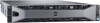
Dell DR6000 Owners Manual
Dell DR6000 Manual
 |
View all Dell DR6000 manuals
Add to My Manuals
Save this manual to your list of manuals |
Dell DR6000 manual content summary:
- Dell DR6000 | Owners Manual - Page 1
Dell DR6000 Systems Owner's Manual Regulatory Model: E14S Series Regulatory Type: E14S001 - Dell DR6000 | Owners Manual - Page 2
the problem. WARNING: A WARNING indicates a potential for property damage, personal injury, or death. © 2013 Dell Inc. All Rights Reserved. Trademarks used in this text: Dell™, the Dell logo, Dell Boomi™, Dell Precision™ , OptiPlex™, Latitude™, PowerEdge™, PowerVault™, PowerConnect™, OpenManage - Dell DR6000 | Owners Manual - Page 3
System Security Screen...23 Miscellaneous Settings...24 System And Setup Password Features 24 Assigning A System Password And/Or Setup Password 25 Deleting Or Changing An Existing System Password And/Or Setup Password 25 Using Your System Password To Secure Your System 26 Operating With A Setup - Dell DR6000 | Owners Manual - Page 4
Inside The System...29 Front Bezel (Optional)...30 Removing The Front Bezel...30 Installing The Front Bezel...31 Opening And Closing The System...31 Opening The System...31 Closing The System...32 Cooling Shroud...32 Removing The Cooling Shroud...32 Installing The Cooling Shroud...33 System Memory - Dell DR6000 | Owners Manual - Page 5
The System Board...84 4 Troubleshooting Your System 85 Safety First-For You And Your System 85 Troubleshooting System Startup Failure 85 Troubleshooting External Connections 85 Troubleshooting The Video Subsystem 85 Troubleshooting A USB Device...85 Troubleshooting A Serial I/O Device 86 - Dell DR6000 | Owners Manual - Page 6
Battery 88 Troubleshooting Power Supplies...88 Troubleshooting Cooling Problems 89 Troubleshooting Cooling Fans...89 Troubleshooting System Memory...89 Troubleshooting An Internal USB Key 90 Troubleshooting A Hard Drive...91 Troubleshooting A Storage Controller 91 Troubleshooting Expansion Cards - Dell DR6000 | Owners Manual - Page 7
About Your System Front-Panel Features And Indicators The following topic describes the front-panel features and indicators of the Dell DR6000 system. Figure 1. Front-Panel Features and Indicators Item 1 Indicator, Button, or Connector Diagnostic indicators Icon 2 System identification button - Dell DR6000 | Owners Manual - Page 8
Description The NMI button is used to troubleshoot software and device driver errors when running button only if directed to do so by qualified support personnel or by the operating system's documentation. which allows you to record system information such as Service Tag, NIC, MAC address, and so on - Dell DR6000 | Owners Manual - Page 9
or System Messages for the specific issue. If it is due to a problem with the power supply, check the LED on the power supply. Re-seat the power supply by removing and reinstalling it. If the problem persists, see Getting Help. Temperature indicator Condition Corrective Action The - Dell DR6000 | Owners Manual - Page 10
any required drivers for the PCIe card. Reinstall the card. If the problem persists, see Getting Help. Hard-Drive Indicator Patterns The following topic describes the hard-drive indicator patterns of the Dell DR6000 system. Figure 2. Hard-Drive Indicators 1. hard-drive activity indicator (green - Dell DR6000 | Owners Manual - Page 11
six seconds Back-Panel Features And Indicators The following topic describes the back-panel features and indicators of the Dell DR6000 system. Figure 3. Back-Panel Features And Indicators Item 1 Indicator, Button, or Connector System identification button Icon Description The identification - Dell DR6000 | Owners Manual - Page 12
hot-swappable 2.5-inch hard drives. Allows you to insert a vFlash media card. NIC Indicator Codes The following topic describes the NIC indicator codes of the Dell DR6000 system. 12 - Dell DR6000 | Owners Manual - Page 13
Figure 4. NIC Indicator 1. link indicator 2. activity indicator Indicator Indicator Code Link and activity The NIC is not connected to the network. indicators are off Link indicator is green The NIC is connected to a valid network at its maximum port speed (1 Gbps or 10 Gbps). Link indicator - Dell DR6000 | Owners Manual - Page 14
Power Indicator Pattern Flashing amber Condition Indicates a problem with the power supply. CAUTION: When correcting Guide that shipped with your system provides an overview of setting up your system, and technical specifications. This document is available online at dell.com/support/manuals. - Dell DR6000 | Owners Manual - Page 15
license purchased. For more information, see the Dell LC2 documentation at dell.com/support/ manuals. Enters the BIOS Boot Manager. Starts Preboot Communication, and then select On with Console Redirection. NOTE: By default, help text for the selected field is displayed in the graphical browser - Dell DR6000 | Owners Manual - Page 16
not take effect until you restart the system. System Setup Options System Setup Main Screen NOTE: Unified Extensible Firmware Interface (UEFI) Boot Manager is not supported. BIOS Boot Manager is the default boot mode. 16 - Dell DR6000 | Owners Manual - Page 17
the system configuration. NOTE: System Setup defaults are listed under their respective options in the system model name, BIOS version, Service Tag, and so on. Memory settings like system password, setup password, TPM security, and so on. It also enables or disables support for local BIOS - Dell DR6000 | Owners Manual - Page 18
if a symmetric memory configuration is installed. If Disabled, the system supports asymmetric NonUniform Memory Architecture (NUMA) memory configurations. By default, Node Interleaving option is set to Disabled. By default, it is set to disabled. Processor Settings Screen Menu Item Logical - Dell DR6000 | Owners Manual - Page 19
Allows you to control the number of enabled cores in each processor. By default, per Processor the Number of Cores per Processor option is set to All. Processor 64-bit Support Specifies if the processor(s) support 64-bit extensions. Processor Core Speed Displays the maximum core frequency of - Dell DR6000 | Owners Manual - Page 20
boot sequence retry feature. If this field is enabled and the system fails to boot, the system reattempts the boot sequence after 30 seconds. By default, the Boot Sequence Retry option is set to Disabled. BIOS Boot Settings Allows you to enable or disable BIOS Boot options. NOTE: This option is - Dell DR6000 | Owners Manual - Page 21
the BIOS configuration of Single Root I/O Virtualization (SR-IOV) devices. By default, the SR-IOV Global Enable option is set to Disabled. Allows you to enable support for PCIe devices that require large amounts of memory. By default, the option is set to Enabled. Allows you to enable or disable - Dell DR6000 | Owners Manual - Page 22
is set to Custom. By default, the System Profile option is set to Performance Per Watt Optimized (DAPC). DAPC is Dell Active Power Controller. NOTE: states. By default, the C States option is set to Enabled. Allows you to enable Monitor/Mwait instructions in the processor. By default, the Monitor - Dell DR6000 | Owners Manual - Page 23
Instruction Set and is set to Enabled by default. Allows you to set the system password. This option is set to Enabled by default and is read-only if the password to Disabled. By default, the BIOS Update Control option is set to Unlocked. NOTE: BIOS updates using the Dell Update Package are not affected - Dell DR6000 | Owners Manual - Page 24
set how the system supports staggering of power up after AC power is restored to the system. By default, the AC Power password, the password jumper must be set to enabled. For more information on the password jumper settings, see System Board Jumper Settings. System password This is the password - Dell DR6000 | Owners Manual - Page 25
, see System Board Jumper Settings. You can assign a new System Password and/or Setup Password or change an existing System Password and/or Setup Password only when the password jumper setting is enabled and Password Status is Unlocked. If the Password Status is Locked, you cannot change the System - Dell DR6000 | Owners Manual - Page 26
before modifying most of the System Setup options. If you do not enter the correct password in three attempts, the system displays the message: Invalid Password! Number of unsuccessful password attempts: System Halted! Must power down. Even after you shut down and restart the system, the - Dell DR6000 | Owners Manual - Page 27
existing system password. NOTE: You can use the Password Status option in conjunction with the Setup Password option to protect the system password from unauthorized Explorer, run the Dell Diagnostics program, and reboot the system. Embedded System Management The Dell Lifecycle Controller provides - Dell DR6000 | Owners Manual - Page 28
the iDRAC7 Enterprise License upgrade. For more information on using iDRAC, see the iDRAC7 User's Guide under Software → Systems Management → Dell Remote Access Controllers, at dell.com/support/manuals. Entering The iDRAC Settings Utility 1. Turn on or reboot the managed system. 2. Press during - Dell DR6000 | Owners Manual - Page 29
only perform troubleshooting and simple repairs as authorized in your product documentation, or as directed by the online or telephone service and support team. Damage due to servicing that is not authorized by Dell is not covered by your warranty. Read and follow the safety instructions that came - Dell DR6000 | Owners Manual - Page 30
Figure 6. Inside the System 1. cooling-fan assembly 3. cooling shroud 5. hard drives (back) (2) 7. network daughter card 9. expansion-card riser 1 11. heat sink for processor 2 13. cooling fans (6) Front Bezel (Optional) 2. cable securing bracket 4. hard-drive backplane (back) 6. expansion-card - Dell DR6000 | Owners Manual - Page 31
only perform troubleshooting and simple repairs as authorized in your product documentation, or as directed by the online or telephone service and support team. Damage due to servicing that is not authorized by Dell is not covered by your warranty. Read and follow the safety instructions that came - Dell DR6000 | Owners Manual - Page 32
only perform troubleshooting and simple repairs as authorized in your product documentation, or as directed by the online or telephone service and support team. Damage due to servicing that is not authorized by Dell is not covered by your warranty. Read and follow the safety instructions that came - Dell DR6000 | Owners Manual - Page 33
only perform troubleshooting and simple repairs as authorized in your product documentation, or as directed by the online or telephone service and support team. Damage due to servicing that is not authorized by Dell is not covered by your warranty. Read and follow the safety instructions that came - Dell DR6000 | Owners Manual - Page 34
of DIMMs populated per channel • DIMM operating voltage • system profile selected (for example, Performance Optimized, Custom, or Dense Configuration Optimized) • maximum supported DIMM frequency of the processors The system contains 24 memory sockets split into two sets of 12 sockets, one set per - Dell DR6000 | Owners Manual - Page 35
Figure 10. Memory Socket Locations Memory channels are organized as follows: Processor 1 channel 0: slots A1, A5, and A9 channel 1: slots A2, A6, and A10 channel 2: slots A3, A7, and A11 channel 3: slots A4, A8, and A12 Processor 2 channel 0: slots B1, B5, and B9 channel 1: slots B2, B6, - Dell DR6000 | Owners Manual - Page 36
to each processor. The allowable configurations depend on the memory mode selected. NOTE: x4 and x8 DRAM based DIMMs can be mixed, providing support for RAS features. However, all guidelines for specific RAS features must be followed. x4 DRAM based DIMMs retain Single Device Data Correction (SDDC - Dell DR6000 | Owners Manual - Page 37
pairs - for example, A1 with A2, A3 with A4, A5 with A6, and so on. Memory Configuration The following table shows the supported memory configuration for a two processor configuration that follows the appropriate memory guidelines stated in this section. NOTE: 2R in the following table indicates - Dell DR6000 | Owners Manual - Page 38
only perform troubleshooting and simple repairs as authorized in your product documentation, or as directed by the online or telephone service and support team. Damage due to servicing that is not authorized by Dell is not covered by your warranty. Read and follow the safety instructions that came - Dell DR6000 | Owners Manual - Page 39
only perform troubleshooting and simple repairs as authorized in your product documentation, or as directed by the online or telephone service and support team. Damage due to servicing that is not authorized by Dell is not covered by your warranty. Read and follow the safety instructions that came - Dell DR6000 | Owners Manual - Page 40
5. If a memory module or a memory-module blank is installed in the socket, remove it. NOTE: Retain removed memory-module blank(s) for future use. 6. Align the memory-module's edge connector with the alignment key of the memory-module socket, and insert the memory module in the socket. NOTE: The - Dell DR6000 | Owners Manual - Page 41
hard drive while the system is running, see the documentation for the storage controller card to ensure that the host adapter is configured correctly to support hot-swap hard drive removal and insertion. CAUTION: Do not turn off or reboot your system while the hard drive is being formatted. Doing so - Dell DR6000 | Owners Manual - Page 42
. 3. If applicable, install the front bezel. Removing A Hot-Swap Hard Drive CAUTION: To prevent data loss, ensure that your operating system supports hot-swap drive installation. See the documentation supplied with your operating system. 1. From the management software, prepare the hard drive for - Dell DR6000 | Owners Manual - Page 43
only perform troubleshooting and simple repairs as authorized in your product documentation, or as directed by the online or telephone service and support team. Damage due to servicing that is not authorized by Dell is not covered by your warranty. Read and follow the safety instructions that came - Dell DR6000 | Owners Manual - Page 44
only perform troubleshooting and simple repairs as authorized in your product documentation, or as directed by the online or telephone service and support team. Damage due to servicing that is not authorized by Dell is not covered by your warranty. Read and follow the safety instructions that came - Dell DR6000 | Owners Manual - Page 45
of a problem with a troubleshooting and simple repairs as authorized in your product documentation, or as directed by the online or telephone service and support team. Damage due to servicing that is not authorized by Dell is not covered by your warranty. Read and follow the safety instructions - Dell DR6000 | Owners Manual - Page 46
only perform troubleshooting and simple repairs as authorized in your product documentation, or as directed by the online or telephone service and support team. Damage due to servicing that is not authorized by Dell is not covered by your warranty. Read and follow the safety instructions that came - Dell DR6000 | Owners Manual - Page 47
only perform troubleshooting and simple repairs as authorized in your product documentation, or as directed by the online or telephone service and support team. Damage due to servicing that is not authorized by Dell is not covered by your warranty. Read and follow the safety instructions that came - Dell DR6000 | Owners Manual - Page 48
only perform troubleshooting and simple repairs as authorized in your product documentation, or as directed by the online or telephone service and support team. Damage due to servicing that is not authorized by Dell is not covered by your warranty. Read and follow the safety instructions that came - Dell DR6000 | Owners Manual - Page 49
only perform troubleshooting and simple repairs as authorized in your product documentation, or as directed by the online or telephone service and support team. Damage due to servicing that is not authorized by Dell is not covered by your warranty. Read and follow the safety instructions that came - Dell DR6000 | Owners Manual - Page 50
only perform troubleshooting and simple repairs as authorized in your product documentation, or as directed by the online or telephone service and support team. Damage due to servicing that is not authorized by Dell is not covered by your warranty. Read and follow the safety instructions that came - Dell DR6000 | Owners Manual - Page 51
only perform troubleshooting and simple repairs as authorized in your product documentation, or as directed by the online or telephone service and support team. Damage due to servicing that is not authorized by Dell is not covered by your warranty. Read and follow the safety instructions that came - Dell DR6000 | Owners Manual - Page 52
only perform troubleshooting and simple repairs as authorized in your product documentation, or as directed by the online or telephone service and support team. Damage due to servicing that is not authorized by Dell is not covered by your warranty. Read and follow the safety instructions that came - Dell DR6000 | Owners Manual - Page 53
only perform troubleshooting and simple repairs as authorized in your product documentation, or as directed by the online or telephone service and support team. Damage due to servicing that is not authorized by Dell is not covered by your warranty. Read and follow the safety instructions that came - Dell DR6000 | Owners Manual - Page 54
6. If you are removing the card permanently, install a metal filler bracket over the empty expansion slot opening and close the expansion-card latch. NOTE: You must install a filler bracket over an empty expansion slot to maintain Federal Communications Commission (FCC) certification of the system. - Dell DR6000 | Owners Manual - Page 55
only perform troubleshooting and simple repairs as authorized in your product documentation, or as directed by the online or telephone service and support team. Damage due to servicing that is not authorized by Dell is not covered by your warranty. Read and follow the safety instructions that came - Dell DR6000 | Owners Manual - Page 56
only perform troubleshooting and simple repairs as authorized in your product documentation, or as directed by the online or telephone service and support team. Damage due to servicing that is not authorized by Dell is not covered by your warranty. Read and follow the safety instructions that came - Dell DR6000 | Owners Manual - Page 57
only perform troubleshooting and simple repairs as authorized in your product documentation, or as directed by the online or telephone service and support team. Damage due to servicing that is not authorized by Dell is not covered by your warranty. Read and follow the safety instructions that came - Dell DR6000 | Owners Manual - Page 58
and Installing the Expansion Card Riser 1 1. expansion-card riser 1 cage 3. riser guide-back (right) 5. expansion-card riser 1 connector 2. expansion-card riser 1 4. riser guide-back (left) 6. riser guide (front) Figure 27. Identifying Connectors on the Expansion Card Riser 1 1. expansion-card - Dell DR6000 | Owners Manual - Page 59
Figure 28. Removing and Installing the Expansion Card Riser 2 1. expansion-card riser 2 3. expansion-card riser 2 connector 2. riser guide (back) 4. riser guide (front) Figure 29. Identifying Connectors on the Expansion Card Riser 2 1. chassis intrusion switch 3. expansion-card slot 5 2. - Dell DR6000 | Owners Manual - Page 60
Figure 30. Removing and Installing the Expansion Card Riser 3 1. riser guide (front) 3. expansion-card riser 3 connector 2. expansion-card riser 3 4. riser guide (back) Figure 31. Identifying Connectors on the Expansion Card Riser 3 1. expansion-card slot 6 2. expansion-card slot 7 4. If - Dell DR6000 | Owners Manual - Page 61
only perform troubleshooting and simple repairs as authorized in your product documentation, or as directed by the online or telephone service and support team. Damage due to servicing that is not authorized by Dell is not covered by your warranty. Read and follow the safety instructions that came - Dell DR6000 | Owners Manual - Page 62
only perform troubleshooting and simple repairs as authorized in your product documentation, or as directed by the online or telephone service and support team. Damage due to servicing that is not authorized by Dell is not covered by your warranty. Read and follow the safety instructions that came - Dell DR6000 | Owners Manual - Page 63
only perform troubleshooting and simple repairs as authorized in your product documentation, or as directed by the online or telephone service and support team. Damage due to servicing that is not authorized by Dell is not covered by your warranty. Read and follow the safety instructions that came - Dell DR6000 | Owners Manual - Page 64
only perform troubleshooting and simple repairs as authorized in your product documentation, or as directed by the online or telephone service and support team. Damage due to servicing that is not authorized by Dell is not covered by your warranty. Read and follow the safety instructions that came - Dell DR6000 | Owners Manual - Page 65
4. Remove the cooling shroud. WARNING: The heat sink and processor are hot to the touch for some time after the system has been powered down. Allow the heat sink and processor to cool before handling them. CAUTION: Never remove the heat sink from a processor unless you intend to remove the processor - Dell DR6000 | Owners Manual - Page 66
9. Similarly, position your thumb firmly over the processor socket-release lever near the lock icon and release the lever from the locked position by pushing down and out from under the tab. Rotate the lever 90 degrees upward. Figure 35. Processor Shield Opening and Closing Lever Sequence 1. close - Dell DR6000 | Owners Manual - Page 67
only perform troubleshooting and simple repairs as authorized in your product documentation, or as directed by the online or telephone service and support team. Damage due to servicing that is not authorized by Dell is not covered by your warranty. Read and follow the safety instructions that came - Dell DR6000 | Owners Manual - Page 68
system, download the latest system BIOS version from support.dell.com and follow the instructions included in the compressed download file to install the open position, align pin 1 of the processor, using pin 1 position guide on the socket, as reference and set the processor lightly in the socket. - Dell DR6000 | Owners Manual - Page 69
the redundant power supply in a sleep state. The power supply defaults are to wake both power supplies if the load on the Guide at dell.com/support/manuals. Removing An AC Power Supply CAUTION: Many repairs may only be done by a certified service technician. You should only perform troubleshooting - Dell DR6000 | Owners Manual - Page 70
only perform troubleshooting and simple repairs as authorized in your product documentation, or as directed by the online or telephone service and support team. Damage due to servicing that is not authorized by Dell is not covered by your warranty. Read and follow the safety instructions that came - Dell DR6000 | Owners Manual - Page 71
4. Connect the power cable to the power supply and plug the cable into a power outlet. CAUTION: When connecting the power cable, secure the cable with the strap. NOTE: When installing, hot-swapping, or hot-adding a new power supply, allow several seconds for the system to recognize the power supply - Dell DR6000 | Owners Manual - Page 72
only perform troubleshooting and simple repairs as authorized in your product documentation, or as directed by the online or telephone service and support team. Damage due to servicing that is not authorized by Dell is not covered by your warranty. Read and follow the safety instructions that came - Dell DR6000 | Owners Manual - Page 73
only perform troubleshooting and simple repairs as authorized in your product documentation, or as directed by the online or telephone service and support team. Damage due to servicing that is not authorized by Dell is not covered by your warranty. Read and follow the safety instructions that came - Dell DR6000 | Owners Manual - Page 74
8. Press the release tabs and slide the backplane upward. Figure 40. Removing and Installing the 3.5 Inch (x12) SAS Backplane 1. release tabs (2) 3. left control panel cable 5. power cable A 7. SAS cables (3) 9. front I/O cable 11. x12 hard-drive backplane 2. pass-through I2C cable 4. I2C cable - Dell DR6000 | Owners Manual - Page 75
only perform troubleshooting and simple repairs as authorized in your product documentation, or as directed by the online or telephone service and support team. Damage due to servicing that is not authorized by Dell is not covered by your warranty. Read and follow the safety instructions that came - Dell DR6000 | Owners Manual - Page 76
only perform troubleshooting and simple repairs as authorized in your product documentation, or as directed by the online or telephone service and support team. Damage due to servicing that is not authorized by Dell is not covered by your warranty. Read and follow the safety instructions that came - Dell DR6000 | Owners Manual - Page 77
6. Lift the backplane to remove it from the chassis. Figure 42. Removing and Installing the Optional 2.5 Inch (x2) Hard-Drive Backplane 1. pass-through I2C cable 3. sideband cable 5. SAS connectors (2) 7. release pin 2. I2C cable 4. hard-drive backplane (back) 6. SAS cable 77 - Dell DR6000 | Owners Manual - Page 78
only perform troubleshooting and simple repairs as authorized in your product documentation, or as directed by the online or telephone service and support team. Damage due to servicing that is not authorized by Dell is not covered by your warranty. Read and follow the safety instructions that came - Dell DR6000 | Owners Manual - Page 79
only perform troubleshooting and simple repairs as authorized in your product documentation, or as directed by the online or telephone service and support team. Damage due to servicing that is not authorized by Dell is not covered by your warranty. Read and follow the safety instructions that came - Dell DR6000 | Owners Manual - Page 80
only perform troubleshooting and simple repairs as authorized in your product documentation, or as directed by the online or telephone service and support team. Damage due to servicing that is not authorized by Dell is not covered by your warranty. Read and follow the safety instructions that came - Dell DR6000 | Owners Manual - Page 81
only perform troubleshooting and simple repairs as authorized in your product documentation, or as directed by the online or telephone service and support team. Damage due to servicing that is not authorized by Dell is not covered by your warranty. Read and follow the safety instructions that came - Dell DR6000 | Owners Manual - Page 82
5. Disconnect the mini SAS cable from the system board: a) Push the mini SAS cable connector to slide it further into the connector (J_SASX8) on the system board. b) Press down and hold the metal tab on the mini SAS cable connector. c) Pull the mini SAS cable out of the connector on the system board - Dell DR6000 | Owners Manual - Page 83
system board toward the front of the system. Figure 45. Removing and Installing the System Board 1. system board 3. release pin 2. system-board holder 4. support bracket (present on certain systems only) WARNING: The heat sink and processor are hot to the touch for some time after the system has - Dell DR6000 | Owners Manual - Page 84
only perform troubleshooting and simple repairs as authorized in your product documentation, or as directed by the online or telephone service and support team. Damage due to servicing that is not authorized by Dell is not covered by your warranty. Read and follow the safety instructions that came - Dell DR6000 | Owners Manual - Page 85
, or as directed by the online or telephone service and support team. Damage due to servicing that is not authorized by Dell is not covered by your warranty. Read and follow the safety instructions that came with the product. Troubleshooting System Startup Failure If you boot the system to - Dell DR6000 | Owners Manual - Page 86
your system and restore the BIOS to the default settings. 9. Reconnect and power on each USB device one at a time. 10. If a device causes the same problem, power down the device, replace the USB cable with a known good cable, and power up the device. If all troubleshooting fails, see Getting Help - Dell DR6000 | Owners Manual - Page 87
only perform troubleshooting and simple repairs as authorized in your product documentation, or as directed by the online or telephone service and support team. Damage due to servicing that is not authorized by Dell is not covered by your warranty. Read and follow the safety instructions that came - Dell DR6000 | Owners Manual - Page 88
troubleshooting and simple repairs as authorized in your product documentation, or as directed by the online or telephone service and support team. Damage due to servicing that is not authorized by Dell is not covered by your warranty. Read and follow the safety instructions If the problem persists, - Dell DR6000 | Owners Manual - Page 89
only perform troubleshooting and simple repairs as authorized in your product documentation, or as directed by the online or telephone service and support team. Damage due to servicing that is not authorized by Dell is not covered by your warranty. Read and follow the safety instructions that came - Dell DR6000 | Owners Manual - Page 90
If the problem is not troubleshooting and simple repairs as authorized in your product documentation, or as directed by the online or telephone service and support team. Damage due to servicing that is not authorized by Dell is not covered by your warranty. Read and follow the safety instructions - Dell DR6000 | Owners Manual - Page 91
service and support team. Damage due to servicing that is not authorized by Dell is not covered by your warranty. Read and follow the safety instructions that came with the product. CAUTION: This troubleshooting and attached peripherals. 8. If the problem is not resolved, turn off the system and - Dell DR6000 | Owners Manual - Page 92
service and support team. Damage due to servicing that is not authorized by Dell is not covered by your warranty. Read and follow the safety instructions that came with the product. NOTE: When troubleshooting connector. 5. Close the system. 6. If the problem is not resolved, turn off the system and - Dell DR6000 | Owners Manual - Page 93
only perform troubleshooting and simple repairs as authorized in your product documentation, or as directed by the online or telephone service and support team. Damage due to servicing that is not authorized by Dell is not covered by your warranty. Read and follow the safety instructions that came - Dell DR6000 | Owners Manual - Page 94
94 - Dell DR6000 | Owners Manual - Page 95
requiring additional equipment or risking data loss. If you are unable to fix the problem yourself, service and support personnel can use the diagnostics results to help you solve the problem. Dell Embedded System Diagnostics NOTE: Also known as Enhanced Pre-boot System Assessment (ePSA) diagnostics - Dell DR6000 | Owners Manual - Page 96
all tests run on the system. This is displayed if at least one event description is recorded. For information about embedded system diagnostics, see the Dell Enhanced Pre-boot System Assessment User Guide at dell.com/support/manuals. 96 - Dell DR6000 | Owners Manual - Page 97
For information on resetting the password jumper to disable a password, see Disabling A Forgotten Password. Table 4. System Board Jumper Settings Jumper Setting Description PWRD_EN (default) The password feature is enabled (pins 4-6). The password feature is disabled (pins 2-4). iDRAC - Dell DR6000 | Owners Manual - Page 98
System Board Connectors Figure 46. System Board Jumpers and Connectors Item 1 2 3 4 5 6 7 8 9 10 11 Connector J_PS2 J_SATA_CD J_SATA_TBU J_BP0 J_TBU J_PS1 J_IDSDM J_NDC J_RISER_3A J_RISER_3B J_USB 98 Description PSU 2 power connector Optical drive SATA connector Tape backup unit SATA connector - Dell DR6000 | Owners Manual - Page 99
Item 12 13 14 15 16 17 18 19 20 21 22 23 24 25 26 27 28 29 30 31 32 33 34 35 36 37 38 39 40 41 42 43 Connector J_VIDEO_REAR J_COM1 J_IDRAC_RJ45 J_CYC CYC_ID J_RISER_2A J_RISER_1A J_RISER_2B J_RISER_1B J_STORAGE J_SASX8 J_USB_INT J_SAS_PCH BAT CPU2 B10, B6, B2, B9, B5, B1 J_BP3 J_BP_SIG3 J_FAN2U_6 - Dell DR6000 | Owners Manual - Page 100
only perform troubleshooting and simple repairs as authorized in your product documentation, or as directed by the online or telephone service and support team. Damage due to servicing that is not authorized by Dell is not covered by your warranty. Read and follow the safety instructions that came - Dell DR6000 | Owners Manual - Page 101
7 Technical Specifications Processor Processor type Two Intel Xeon processor E5-2670 product family Power AC Power Supply (per power supply) Wattage 1100 W Heat dissipation 4100 BTU/hr (maximum) NOTE: Heat dissipation is calculated using the power supply wattage rating. Voltage 100-240 V - Dell DR6000 | Owners Manual - Page 102
Memory module sockets Memory module capacities RAM 800 MT/s, 1066 MT/s, 1333 MT/s or 1600 MT/s DDR3 registered Error Correcting Code (ECC) DIMMs Support for advanced ECC or memory optimized operation Twenty-four 240-pin 8 GB dual ranked RDIMMs 32 GB with two processors Drives Hard drives Up to - Dell DR6000 | Owners Manual - Page 103
m (10,000 ft). • 130 W (4 core) processor is not supported. • Redundant power supplies are required. • Non-Dell qualified peripheral cards and/or peripheral cards greater than 25 W are not supported. • Maximum 95 W processor is supported on 3.5 inch hard drive chassis. • Maximum 115 W processor is - Dell DR6000 | Owners Manual - Page 104
Environmental Temperature Ranges (for altitude less than 950 m 10 °C to 35 °C (50 °F to 95 °F) with no direct or 3117 ft) sunlight on the equipment. Humidity Percentage Range 10% to 80% Relative Humidity with 26 °C (78.8 °F) maximum dew point. Relative Humidity Storage 5% to 95% RH with 33 - Dell DR6000 | Owners Manual - Page 105
Environmental Air Filtration Data center air filtration as defined by ISO Class NOTE: Applies to data center environments only. Air filtration requirements do not apply 8 per ISO 14644-1 with a 95% upper confidence limit. to IT equipment designed to be used outside NOTE: Air entering the data - Dell DR6000 | Owners Manual - Page 106
106 - Dell DR6000 | Owners Manual - Page 107
8 System Messages System Error Messages System messages appear on the monitor to notify you of a possible problem with the system. These messages refer to events recorded in the System Event Log (SEL). For information on the SEL and configuring system management settings, - Dell DR6000 | Owners Manual - Page 108
The battery has failed. The battery is either missing, bad, or unable to charge due to thermal issues. Check system fans. If the problem persists, see Getting Help. Message CPU has an internal error (IERR). 108 - Dell DR6000 | Owners Manual - Page 109
temperature (if available) and reinstall processor heat sink. If the problem persists, see Getting Help. Message Details Action CPU configuration run in a degraded state. Review the technical specifications for supported processor types. Message Details Action CPU is throttled - Dell DR6000 | Owners Manual - Page 110
Error Code CPU0701 CPU0702 CPU0703 110 Message Information Action 1. 2. 3. 4. Turn off the system and remove input power for one minute. Ensure the processor is seated correctly. Reapply input power and turn on the system. If the issue persists, see Getting Help. Message Details Action CPU < - Dell DR6000 | Owners Manual - Page 111
Error Code CPU0704 FAN0000 FAN0001 FAN1201 HWC1001 HWC2003 Message Information 5. If the issue persists, see Getting Help. Message Details Action CPU machine check error detected. System event log and operating system logs may indicate that the exception is external to the processor. 1. - Dell DR6000 | Owners Manual - Page 112
Error Code HWC2005 MEM0000 MEM0001 MEM0007 MEM0701 MEM0702 Message Information Action Check if the cable is present, then reinstall or reconnect. Message Details Action The system board cable is not connected, or is improperly connected. The cable may be necessary for proper operation. - Dell DR6000 | Owners Manual - Page 113
Error Code MEM1205 MEM1208 MEM8000 PCI1302 PCI1304 PCI1308 Message Information Details The memory may not be operational. This an early indicator of a possible future uncorrectable error. Action Re-seat the memory modules. If the issue persists, see Getting Help. Message Details Action Memory - Dell DR6000 | Owners Manual - Page 114
Error Code PCI1320 PCI1342 PCI1348 PCI1360 PDR0001 Message Information Details System performance may be degraded, PCI device may fail to operate, or system may fail to operate. Action Cycle input power, update component drivers, if device is removable, reinstall the device. Message Details - Dell DR6000 | Owners Manual - Page 115
memory for system operation. Compare system memory installation to supported system memory configurations. Message Action Power supply degraded or lost. Remove and reinstall the power supply at the next service window. If the issue persists, see Getting Help. Message Details Action - Dell DR6000 | Owners Manual - Page 116
Error Code PSU0016 PSU0031 PSU0032 PSU0033 PSU0034 116 Message Information Action Install matched power supplies and review proper configuration in this manual. Message Details Action Power supply is absent. The power supply has been removed or has failed. 1. Remove and reinstall the - Dell DR6000 | Owners Manual - Page 117
on power supply . Check for fan blockage. If the problem persists, see Getting Help. A power supply wattage mismatch is detected input type and power rating. Install matched power supplies and review this manual for proper configuration. Power supply redundancy is lost. The power supply - Dell DR6000 | Owners Manual - Page 118
Failure detected on Removable Flash Media . An error was reported during a SD card read or write. Reseat the flash media. If the problem persists, see Getting Help. Message Details Action Removable Flash Media is write protected. The card is write-protected by the physical latch on - Dell DR6000 | Owners Manual - Page 119
Error Code RFM2001 RFM2002 RFM2004 RFM2006 SEC0031 SEC0033 SEL0006 Message Information Message Details Action Internal Dual SD Module is absent. The SD card module is not detected or not installed. If unintended, reinstall the SD module. Message Details Action Internal Dual SD Module < - Dell DR6000 | Owners Manual - Page 120
. Some management software do not report platform exceptions. Reboot the management controller or iDRAC. Cycle system input power. If problem persists call support. Message Details Action An unknown system hardware failure detected. If the system event log failed to initialize, platform status and - Dell DR6000 | Owners Manual - Page 121
configuration, inspect and reinstall system cables. 3. If the issue persists, see Getting Help. Warning Messages A warning message alerts you to a possible problem and prompts you to respond before the system continues a task. For example, before you format a hard drive, a message warns you that - Dell DR6000 | Owners Manual - Page 122
122 - Dell DR6000 | Owners Manual - Page 123
menu at the top of page. 4. Select the appropriate service or support link based on your need. Related Documentation NOTE: For all PowerEdge and PowerVault documentation, go to dell.com/support/manuals and enter the system Service Tag to get your system documentation. NOTE: For all Virtualization - Dell DR6000 | Owners Manual - Page 124
Documentation Feedback If you have feedback for this document, write to [email protected]. Alternatively, you can click on the Feedback link in any of the Dell documentation pages, fill out the form, and click Submit to send your feedback. 124
-
 1
1 -
 2
2 -
 3
3 -
 4
4 -
 5
5 -
 6
6 -
 7
7 -
8
-
9
-
10
-
11
-
12
-
13
-
14
-
15
-
16
-
17
-
18
-
19
-
20
-
21
-
22
-
23
-
24
-
25
-
26
-
27
-
28
-
29
-
30
-
31
-
32
-
33
-
34
-
35
-
36
-
37
-
38
-
39
-
40
-
41
-
42
-
43
-
44
-
45
-
46
-
47
-
48
-
49
-
50
-
51
-
52
-
53
-
54
-
55
-
56
-
57
-
58
-
59
-
60
-
61
-
62
-
63
-
64
-
65
-
66
-
67
-
68
-
69
-
70
-
71
-
72
-
73
-
74
-
75
-
76
-
77
-
78
-
79
-
80
-
81
-
82
-
83
-
84
-
85
-
86
-
87
-
88
-
89
-
90
-
91
-
92
-
93
-
94
-
95
-
96
-
97
-
98
-
99
-
100
-
101
-
102
-
103
-
104
-
105
-
106
-
107
-
108
-
109
-
110
-
111
-
112
-
113
-
114
-
115
-
116
-
117
-
118
-
119
-
120
-
121
-
122
-
123
-
124
 |
 |

Dell DR6000 Systems
Owner's Manual
Regulatory Model: E14S Series
Regulatory Type: E14S001