D-Link DGS-3130 Quick Install Guide
D-Link DGS-3130 Manual
 |
View all D-Link DGS-3130 manuals
Add to My Manuals
Save this manual to your list of manuals |
D-Link DGS-3130 manual content summary:
- D-Link DGS-3130 | Quick Install Guide - Page 1
- D-Link DGS-3130 | Quick Install Guide - Page 2
DGS-3130 Series Layer 3 Stackable Managed Switch Hardware Installation Guide Information in this document is subject to change without notice. Reproduction in any manner whatsoever, without the written permission of D-Link Corporation, is strictly forbidden. Trademarks used in this text: D-Link and - D-Link DGS-3130 | Quick Install Guide - Page 3
according to the instructions of the manufacturer. PoE Load Condition: - For AC or DC input: 30W per each PoE port, total: 370W maximum (for DGS-3130-30PS & DGS-3130-54PS) - For AC and DC input: 30W per each PoE port, total: 740W maximum (for DGS-3130-30PS & DGS-3130-54PS) To reduce potential - D-Link DGS-3130 | Quick Install Guide - Page 4
DGS-3130 Series Layer 3 Stackable Managed Switch Hardware Installation Guide contains detailed information about the hardware specifications of the switches in this series. It also contains brief information on how to configure and manage a switch in this series. This manual Instructions service - D-Link DGS-3130 | Quick Install Guide - Page 5
DGS-3130 Series Layer 3 Stackable Managed Switch Hardware Installation Guide • The product has been dropped or damaged. • The product does not operate correctly when the operating instructions environment. If the system gets wet contact your trained service provider. • Do not push any objects into - D-Link DGS-3130 | Quick Install Guide - Page 6
DGS-3130 Series Layer 3 Stackable Managed Switch Hardware Installation Guide General Precautions for Rack-Mountable components in the rack. • Do not step on or stand on any component when servicing other components in a rack. CAUTION: Never defeat the ground conductor or operate the equipment - D-Link DGS-3130 | Quick Install Guide - Page 7
...12 DGS-3130-30TS Switch...12 Front Panel Components...12 LED Indicators ...12 Rear Panel Components ...14 Side Panel Components ...14 DGS-3130-30S Switch ...15 Front Panel Components...15 LED Indicators ...15 Rear Panel Components ...17 Side Panel Components ...17 DGS-3130-30PS Switch ...18 - D-Link DGS-3130 | Quick Install Guide - Page 8
DGS-3130 Series Layer 3 Stackable Managed Switch Hardware Installation Guide Installing the the MGMT Port ...53 Connecting using SNMP ...54 Traps ...54 Management Information Base (MIB)...54 6. Web-based Switch Configuration ...55 Introduction ... Cable ...66 Warranty ...68 Technical Support viii - D-Link DGS-3130 | Quick Install Guide - Page 9
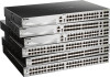
that may span great distances. The D-Link DGS-3130 Series includes the following switches: • DGS-3130-30TS supports twenty-four RJ45 ports (10/100/1000 Mbps), two 10G RJ45 ports (10 Gigabit), and four SFP+ ports (10 Gigabit). • DGS-3130-30S supports twenty-four SFP ports (100/1000 Mbps), two 10G - D-Link DGS-3130 | Quick Install Guide - Page 10
DGS-3130 Series Layer 3 Stackable Managed Switch Hardware Installation Guide Features This switch is packed with an abundance of networking features that span inside and outside of the traditional Layer 3 framework. The list below highlights the significant protocols and features supported Service - D-Link DGS-3130 | Quick Install Guide - Page 11
DGS-3130 Series Layer 3 Stackable Managed Switch Hardware Installation Guide • Microsoft® NAP Support (IPv4/IPv6)1 • Cable Diagnostics • 802.3ah Ethernet Link OAM • 802.1ag Connectivity Fault Management (CFM)1 • Y.1731 OAM1 • Optical Transceiver Digital Diagnostic Monitoring (DDM) • D-Link - D-Link DGS-3130 | Quick Install Guide - Page 12
Guide 2. Hardware Components This chapter describes the front, rear, and side panel components of all switches in the series. DGS-3130-30TS Switch DGS-3130-30S Switch DGS-3130-30PS Switch DGS-3130-54TS Switch DGS-3130-54S Switch DGS-3130-54PS Switch DGS-3130-30TS firmware -speeds and support a wide - D-Link DGS-3130 | Quick Install Guide - Page 13
Hardware Installation Guide LED Power Console MGMT RPS Fan Err USB Link/Act LEDs Figure 2-2 LED indicators for the DGS-3130-30TS Description This of MGMT port. This LED will light solid green or amber after a link to the MGMT port was successfully established. This LED will blink when activity - D-Link DGS-3130 | Quick Install Guide - Page 14
DGS-3130 Series Layer 3 Stackable Managed Switch Hardware Installation Guide Description This 7-segment LED can display numbers from 1 to 9 and the following letters H, h, E, and G. The stacking ID (1 to 9) can be assigned manually Rear panel view of the DGS-3130-30TS Components that can be found - D-Link DGS-3130 | Quick Install Guide - Page 15
Guide Figure 2-4 Side panels of the DGS-3130-30TS DGS-3130-30S Switch Front Panel Components The front panel of DGS-3130-30S features a variety of LED indicators and ports. Figure 2-5 Front panel view of the DGS-3130-30S firmware and support a Link/Act indicators for all the ports, and Stack ID. 15 - D-Link DGS-3130 | Quick Install Guide - Page 16
Hardware Installation Guide LED Power Console MGMT RPS Fan Err USB Link/Act LEDs Figure 2-6 LED indicators for the DGS-3130-30S Description This LED of MGMT port. This LED will light solid green or amber after a link to the MGMT port was successfully established. This LED will blink when activity - D-Link DGS-3130 | Quick Install Guide - Page 17
DGS-3130 Series Layer 3 Stackable Managed Switch Hardware Installation Guide Description when a 10 Gbps port is active or blink amber when a 1 Gbps port is active. The LED will be off when there is no link . Figure 2-7 Rear Panel view of the DGS-3130-30S Components that can be found on the rear - D-Link DGS-3130 | Quick Install Guide - Page 18
Guide Figure 2-8 Side panels of the DGS-3130-30S DGS-3130-30PS Switch Front Panel Components The front panel of DGS-3130-30PS features a variety of LED indicators and ports. Figure 2-9 Front panel view of the DGS-3130-30PS and 10 Gbps wire-speeds and support a wide collection of SFP+ transceivers - D-Link DGS-3130 | Quick Install Guide - Page 19
Series Layer 3 Stackable Managed Switch Hardware Installation Guide LED Power Console MGMT RPS Fan Err USB Link/Act LEDs Figure 2-10 LED indicators for the DGS-3130-30PS Description This LED will light solid green after the Switch has been powered on successfully. This LED will be off when the - D-Link DGS-3130 | Quick Install Guide - Page 20
DGS-3130 Series Layer 3 Stackable Managed Switch Hardware Installation Guide E, and G. The stacking ID (1 to 9) can be assigned manually by the user or automatically by the system. The letter 'H' will supply. Figure 2-11 Rear panel view of the DGS-3130-30PS Components that can be found on the rear - D-Link DGS-3130 | Quick Install Guide - Page 21
DGS-3130-30PS DGS-3130-54TS Switch Front Panel Components The front panel of DGS-3130-54TS features a variety of LED indicators and ports. Figure 2-13 Front panel view of the DGS-3130-54TS Gbps wire-speeds and support a wide collection of SFP Link/Act indicators for all the ports, and Stack ID. 21 - D-Link DGS-3130 | Quick Install Guide - Page 22
Guide LED Power Console MGMT RPS Fan Err USB Link/Act LEDs Stack ID Figure 2-14 LED indicators for the DGS-3130-54TS or amber after a link to the MGMT Link and Activity. 1G RJ45 Ports: The LED at the left side indicates the Link off when there is no link or activity. This 7-segment LED can display - D-Link DGS-3130 | Quick Install Guide - Page 23
DGS-3130 Series Layer 3 Stackable Managed Switch Hardware Installation Guide supply. Figure 2-15 Rear panel view of the DGS-3130-54TS Components that can be found on the rear panel port provides an additional storage space for portable firmware images and configuration files that can be copied to - D-Link DGS-3130 | Quick Install Guide - Page 24
DGS-3130-54TS DGS-3130-54S Switch Front Panel Components The front panel of DGS-3130-54S features a variety of LED indicators and ports. Figure 2-17 Front panel view of the DGS-3130-54S 10 Gbps wire-speeds and support a wide collection of SFP+ Link/Act indicators for all the ports, and Stack ID. 24 - D-Link DGS-3130 | Quick Install Guide - Page 25
Hardware Installation Guide LED Power Console MGMT RPS Fan Err USB Link/Act LEDs Figure 2-18 LED indicators for the DGS-3130-54S Description This of MGMT port. This LED will light solid green or amber after a link to the MGMT port was successfully established. This LED will blink when activity - D-Link DGS-3130 | Quick Install Guide - Page 26
DGS-3130 Series Layer 3 Stackable Managed Switch Hardware Installation Guide Description when a 10 Gbps port is active or blink amber when a 1 Gbps port is active. The LED will be off when there is no link view of the DGS-3130-54S Components that space for portable firmware images and configuration - D-Link DGS-3130 | Quick Install Guide - Page 27
DGS-3130-54S DGS-3130-54PS Switch Front Panel Components The front panel of DGS-3130-54PS features a variety of LED indicators and ports. Figure 2-21 Front panel view of the DGS-3130-54PS 10 Gbps wire-speeds and support a wide collection of SFP Link/Act indicators for all the ports, and Stack ID. 27 - D-Link DGS-3130 | Quick Install Guide - Page 28
Series Layer 3 Stackable Managed Switch Hardware Installation Guide LED Power Console MGMT RPS Fan Err USB Link/Act LEDs PoE Figure 2-22 LED indicators for the DGS-3130-54PS Description This LED will light solid green after the Switch has been powered on successfully. This LED will be off when - D-Link DGS-3130 | Quick Install Guide - Page 29
DGS-3130 Series Layer 3 Stackable Managed Switch Hardware Installation Guide stacking ID (1 to 9) can be assigned manually by the user or automatically by the system. Rear panel view of the DGS-3130-54PS Components that can be found storage space for portable firmware images and configuration files - D-Link DGS-3130 | Quick Install Guide - Page 30
DGS-3130 Series Layer 3 Stackable Managed Switch Hardware Installation Guide Component Console (RJ45) Description speed. This port can be used to configure the Switch without being could lead to system failure or even severely damaged components. Figure 2-24 Side panels of the DGS-3130-54PS 30 - D-Link DGS-3130 | Quick Install Guide - Page 31
DGS-3130 Series Layer 3 Stackable Managed Switch Hardware Installation Guide 3. Installation Installation Guidelines Installing the Switch feet to the Switch Install the Switch on a sturdy, level surface that can support the weight of the Switch (see the Weight section in Appendix A - Technical - D-Link DGS-3130 | Quick Install Guide - Page 32
DGS-3130 Series Layer 3 Stackable Managed Switch Hardware Installation Guide Installing the Switch in a Standard 19" Rack This section is used to guide to connect various other networking devices to this switch that do not support the standard RJ45 wiring connection. These ports are generally used to - D-Link DGS-3130 | Quick Install Guide - Page 33
DGS-3130 Series Layer 3 Stackable Managed Switch Hardware Installation Guide Figure 3-4 Inserting transceivers into the transceiver ports The SFP+ ports also support other transceiver form factors like SFP and SFP+ transceivers. A complete list of SFP/SFP+ transceivers, compatible with this switch, - D-Link DGS-3130 | Quick Install Guide - Page 34
DGS-3130 Series Layer 3 Stackable Managed Switch Hardware Installation Guide Figure 3-5 Insert Tie Wrap into the Switch 2. Plug the AC power cord into the power socket of the Switch. Figure 3-6 Connect the power cord to - D-Link DGS-3130 | Quick Install Guide - Page 35
DGS-3130 Series Layer 3 Stackable Managed Switch Hardware Installation Guide Figure 3-8 Circle around the power cord 5. Fasten the tie of the retainer until the power cord is secured. Figure 3-9 Secure the power cord Installing the - D-Link DGS-3130 | Quick Install Guide - Page 36
NOTE: See the DPS-500A documentation for more information. NOTE: For DGS-3130-30PS/54PS PoE models, DPS-700 is selected as redundant power supply or PoE to two RPS units. NOTE: This rack-mount chassis supports the following RPS units: DPS-500A. The following diagram illustrates how a DPS-500A is - D-Link DGS-3130 | Quick Install Guide - Page 37
DGS-3130 Series Layer 3 Stackable Managed Switch Hardware Installation Guide Figure 3-11 Install the DPS-500A in the DPS-800 The DPS-800 can be mounted into a standard 19" rack, as shown below. Figure 3-12 - D-Link DGS-3130 | Quick Install Guide - Page 38
DGS-3130 Series Layer 3 Stackable Managed Switch Hardware Installation Guide Figure 3-13 Front view of the DPS- in operation. 4. No configuration in the Switch's firmware is needed for this installation. NOTE: See the RPS Quick Installation Guide for more information. CAUTION: This equipment is to - D-Link DGS-3130 | Quick Install Guide - Page 39
DGS-3130 Series Layer 3 Stackable Managed Switch Hardware Installation Guide 4. Switch Connections Switch to an End Node Switch to Switch via a twisted pair Category 5e UTP/STP cable. • Connect a switch supporting an optical fiber uplink to the Switch's SFP/SFP+ ports via fiber optical cabling. 39 - D-Link DGS-3130 | Quick Install Guide - Page 40
per stack. If the stack is constructed of DGS-3130-54TS/54S/54PS series, the maximum stacking number is 6 devices per stack due to stacking cost of DGS-313054TS/54S/54PS is two. If the stack is constructed of DGS-3130-30TS/30S/30PS and DGS-313054TS/54S/54PS series, the stacking number is limited by - D-Link DGS-3130 | Quick Install Guide - Page 41
DGS-3130 Series Layer 3 Stackable Managed Switch Hardware Installation Guide 8 2 9 1 10 0 5 7 12 5 6 11 6 6 12 The figure below illustrates how switches can be stacked in a Duplex Chain formation using RJ45 cables, optical fiber cables connected to - D-Link DGS-3130 | Quick Install Guide - Page 42
DGS-3130 Series Layer 3 Stackable Managed Switch Hardware Installation Guide Figure 4-4 2-Port Duplex Chain stacking topology (SFP+ ports) 42 - D-Link DGS-3130 | Quick Install Guide - Page 43
DGS-3130 Series Layer 3 Stackable Managed Switch Hardware Installation Guide Figure 4-5 4-Port Duplex Chain stacking topology (10GBase-T and SFP+ ports) 43 - D-Link DGS-3130 | Quick Install Guide - Page 44
DGS-3130 Series Layer 3 Stackable Managed Switch Hardware Installation Guide Figure 4-6 4-Port Duplex Chain stacking topology (SFP+ ports) 44 - D-Link DGS-3130 | Quick Install Guide - Page 45
DGS-3130 Series Layer 3 Stackable Managed Switch Hardware Installation Guide The figure below illustrates how switches can be stacked in a Duplex Ring formation using RJ45 cables, optical fiber cables connected to SFP+ transceivers or DAC - D-Link DGS-3130 | Quick Install Guide - Page 46
DGS-3130 Series Layer 3 Stackable Managed Switch Hardware Installation Guide Figure 4-8 2-port Duplex Ring stacking topology (SFP+ ports) 46 - D-Link DGS-3130 | Quick Install Guide - Page 47
DGS-3130 Series Layer 3 Stackable Managed Switch Hardware Installation Guide Figure 4-9 4-port Duplex Ring stacking topology (10GBase-T and SFP+ ports) 47 - D-Link DGS-3130 | Quick Install Guide - Page 48
DGS-3130 Series Layer 3 Stackable Managed Switch Hardware Installation Guide Figure 4-10 4-port Duplex Ring stacking topology (SFP+ ports) NOTE: When 4-port duplex ring with 10GBase-T and SFP+ port topology is used and odd number - D-Link DGS-3130 | Quick Install Guide - Page 49
DGS-3130 Series Layer 3 Stackable Managed Switch Hardware Installation Guide Switch to a Server The Switch is ideal for connecting to a network backbone, server, or server farm. The RJ45 ports operate at a speed of 10/100/ - D-Link DGS-3130 | Quick Install Guide - Page 50
switch management features. For more detailed information about the CLI, refer to the DGS-3130 Series CLI Reference Guide. SNMP-based Management The Switch can be managed with a SNMP-compatible console program. The Switch supports SNMP v1, SNMPv2c and SNMPv3. The SNMP agent decodes the incoming SNMP - D-Link DGS-3130 | Quick Install Guide - Page 51
DGS-3130 Series Layer 3 Stackable Managed Switch Hardware Installation Guide To configure the terminal emulation software as follows Procedure V1.00.001 Power On Self Test 100 % MAC Address : F0-7D-68-36-30-00 H/W Version : A1 Please Wait, Loading 1.00.001 Runtime Image UART init Starting - D-Link DGS-3130 | Quick Install Guide - Page 52
DGS-3130 Series Layer 3 Stackable Managed Switch Hardware Installation Guide Connecting to the Switch for the First Time The Switch supports user- example below). DGS-3130-30TS Gigabit Ethernet Switch Switch> Command Line Interface Firmware: Build 1.00.001 Copyright(C) 2017 D-Link Corporation. All - D-Link DGS-3130 | Quick Install Guide - Page 53
DGS-3130 Series Layer 3 Stackable Managed Switch Hardware Installation Guide NOTE: Passwords are case sensitive. MGMT port, use the following command: Switch#show ip interface mgmt 0 mgmt_ipif 0 is enabled, Link status is up IP address is 192.168.0.1/24 Gateway is 0.0.0.0 Switch# The IP settings or - D-Link DGS-3130 | Quick Install Guide - Page 54
DGS-3130 Series Layer 3 Stackable Managed Switch Hardware Installation Guide problems in the Switch, switch group, or network. Managed devices that support over the network. The Switch supports SNMPv1, SMNPv2c, and SNMPv3. MIB-II, the Switch also supports its own proprietary enterprise MIB - D-Link DGS-3130 | Quick Install Guide - Page 55
DGS-3130 Series Layer 3 Stackable Managed Switch Hardware Installation Guide 6. Web-based Switch Configuration with the Switch using the HTTP or HTTPS (SSL) protocol. The following web browsers are supported: • Internet Explorer (version 7 and later) • Firefox • Google Chrome • Safari Logging - D-Link DGS-3130 | Quick Install Guide - Page 56
DGS-3130 Series Layer 3 Stackable Managed Switch Hardware Installation Guide NOTE: After a user account was created, functions, including port monitoring, are accessible from here. Click the D-Link logo to go to the D-Link website. This area displays a file explorer-type menu tree with all - D-Link DGS-3130 | Quick Install Guide - Page 57
DGS-3130 Series Layer 3 Stackable Managed Switch Hardware Installation Guide Web and configured in this folder. Features regarding the Quality of Service functionality of the Switch can be viewed and configured in regarding the D-Link Green Technology can be viewed and configured in this folder. - D-Link DGS-3130 | Quick Install Guide - Page 58
only supports FAT16 and FAT32 file system architectures DGS-3130-30TS: 30.76W (Max.), 23.20W (Standby) DGS-3130-30S: 82.4W (Max.), 43.9W (Standby) DGS-3130-30PS: 471.67W (Max.), 52.44W (Standby) DGS-3130-54TS: 50.62W (Max.), 38.67W (Standby) DGS-3130-54S: 131W (Max.), 68.7W (Standby) DGS-3130-54PS - D-Link DGS-3130 | Quick Install Guide - Page 59
size DGS-3130-30TS: 2.98Kg DGS-3130-30S: 3.21Kg DGS-3130-30PS: 4.66Kg DGS-3130-54TS: 3.72Kg DGS-3130-54S: 4.52Kg DGS-3130-54PS: 5.14Kg DGS-3130-30TS: 900,546 Hours DGS-3130-30S: 487,153 Hours DGS-3130-30PS: 409,054 Hours DGS-3130-54TS: 478,258 Hours DGS-3130-54S: 520,861 Hours DGS-3130-54PS: 356 - D-Link DGS-3130 | Quick Install Guide - Page 60
DGS-3130-54PS: 216 Gbps DGS-3130-30TS: 125 Mpps DGS-3130-30S: 125 Mpps DGS-3130-30PS: 125 Mpps DGS-3130-54TS: 161 Mpps DGS-3130-54S: 161 Mpps DGS-3130-54PS: 161 Mpps 8 Priority Queues per port. Supports 16K (16,384) MAC addresses IPv4: Max. 512 entries IPv6: Max. 512 entries Supports D-Link Single - D-Link DGS-3130 | Quick Install Guide - Page 61
DGS-3130 Series Layer 3 Stackable Managed Switch Hardware Installation Guide Location LED Per 10/100/1000 Mbps Port LED Link/Act/Speed Mode LED Per 10 Gbps Port Link/Act/Speed Mode LED per SFP Port Link/Act LED per SFP+ Link/Act Port Color Green Amber Off Green Amber Off Green Amber Off - D-Link DGS-3130 | Quick Install Guide - Page 62
DGS-3130 Series Layer 3 Stackable Managed Switch Hardware Installation Guide Port Functions Feature RJ45 single-mode, 50 km) • DEM-315GT (1000BASE-ZX, single-mode, 80 km) • DGS-712 (1000BASE-T) WDM (BiDi) SFP Transceivers Supported: • DEM-220T (100BASE-BX-D, single-mode, 20 km, TX: 1550 nm / RX: - D-Link DGS-3130 | Quick Install Guide - Page 63
Feature DGS-3130 Series Layer 3 Stackable Managed Switch Hardware Installation Guide Description • DEM-436XT-BXU (10GBASE-LR, single-mode, 20 km, TX: 1270 nm / RX: 1310 nm, without DDM) SFP+ Direct Attached Cables (DAC) Supported: • DEM-CB100S (10G SFP+, 1 m) for stacking or uplink connection • DEM - D-Link DGS-3130 | Quick Install Guide - Page 64
DGS-3130 Series Layer 3 Stackable Managed Switch Hardware Installation Guide Appendix B - Cables and Connectors Ethernet Cable When connecting the Switch to another switch, a bridge or hub, a straight-through Cat5/5e/6a/7 cable is necessary. Please - D-Link DGS-3130 | Quick Install Guide - Page 65
DGS-3130 Series Layer 3 Stackable Managed Switch Hardware Installation Guide Console Cable (RJ45 to RS-232) A console cable is used to connect to the RJ45 console port of the Switch to access the command line - D-Link DGS-3130 | Quick Install Guide - Page 66
DGS-3130 Series Layer 3 Stackable Managed Switch Hardware Installation Guide Redundant Power Supply (RPS) Cable When connecting the Switch to a Redundant Power Supply, an RPS cable is necessary. Please review this product for matching cable - D-Link DGS-3130 | Quick Install Guide - Page 67
DGS-3130 Series Layer 3 Stackable Managed Switch Hardware Installation Guide Figure B-4 RPS Cable for DPS-700 (22-pin Power Cable) Pin Device DPS-700 1 -54Vrtn -54Vrtn 2 -54V -54V 3 +12V +12V 4 +12V +12V 5 +12V +12V 6 +12V + - D-Link DGS-3130 | Quick Install Guide - Page 68
DGS-3130 Series Layer 3 Stackable Managed Switch Hardware Installation Guide Warranty Subject to the terms and conditions set forth herein, D-Link Systems, Inc. ("D-Link") provides this lifetime product warranty for hardware: • Only for products purchased, delivered and used within the fifty states - D-Link DGS-3130 | Quick Install Guide - Page 69
DGS-3130 Series Layer 3 Stackable Managed Switch Hardware Installation Guide LINK FOR WARRANTY SERVICE) RESULTING FROM THE USE OF THE PRODUCT, RELATING TO WARRANTY SERVICE, OR ARISING OUT OF ANY BREACH OF THIS WARRANTY, EVEN IF D-LINK in accordance with the instructions, may cause harmful interference - D-Link DGS-3130 | Quick Install Guide - Page 70
DGS-3130 Series Layer 3 Stackable Managed Switch Hardware Installation Guide Technical Support U.S. and Canadian customers This guide is only for initial configuration. Please refer to the user manual to learn more or visit http://www.mydlink.com for more information. Also feel free to contact us. - D-Link DGS-3130 | Quick Install Guide - Page 71
DGS-3130 Series Layer 3 Stackable Managed Switch Hardware Installation Guide Europe customers TECHNICAL SUPPORT TECHNISCHE UNTERSTÜTZUNG ASSISTANCE TECHNIQUE ASISTENCIA TÉCNICA SUPPORTO TECNICO TECHNISCHE ONDERSTEUNING POMOC TECHNICZNA TECHNICKÁ PODPORA TECHNIKAI TÁMOGATÁS TEKNISK STØTTE TEKNISK - D-Link DGS-3130 | Quick Install Guide - Page 72
DGS-3130 Series Layer 3 Stackable Managed Switch Hardware Installation Guide Australia: Tel: 1300-700-100 24/7 Technical Support Web: http://www.dlink.com.au E-mail: [email protected] India: Tel: +91-832-2856000 or 1860-233-3999 Web: www.dlink.co.in E-Mail: [email protected] Singapore, - D-Link DGS-3130 | Quick Install Guide - Page 73
DGS-3130 Series Layer 3 Stackable Managed Switch Hardware Installation Guide Egypt: Technical Support Call Center: +20 2258 66777 General Inquiries: [email protected] Tech Support : [email protected] Kingdom of Saudi Arabia: Technical Support: +966 1121 70009 General Inquiries: info.sa@me. - D-Link DGS-3130 | Quick Install Guide - Page 74
DGS-3130 Series Layer 3 Stackable Managed Switch Hardware Installation Guide D-Link. D-Link D-Link D-Link D-Link: 8-800-700-5465 http://www.dlink.ru e-mail: [email protected] 11494 3 289 390043 16 Тел.: +7 (4912) 575-305 ОФИСЫ 14 Тел. : +7 (495) 744-00-99 E-mail: [email protected] - D-Link DGS-3130 | Quick Install Guide - Page 75
DGS-3130 Series Layer 3 Stackable Managed Switch Hardware Installation Guide Rīga, Lielirbes iela 27 Tel.: +371 (6) 761- [email protected] 20 072-2575555 [email protected] SOPORTE TÉCNICO Usted puede encontrar actualizaciones de softwares o firmwares y documentación para usuarios a través de - D-Link DGS-3130 | Quick Install Guide - Page 76
DGS-3130 Series Layer 3 Stackable Managed Switch Hardware Installation Guide D-Link D-Link 台灣D-Link 0800-002-615 02) 6600-0123#8715 http://www.dlink.com.tw [email protected] http://www.dlinktw.com.tw/techsupport D-Link 852 - 8100 8892 / 澳門 853 - 2875 3423 http://www.dlink.
-
 1
1 -
 2
2 -
 3
3 -
 4
4 -
 5
5 -
 6
6 -
 7
7 -
8
-
9
-
10
-
11
-
12
-
13
-
14
-
15
-
16
-
17
-
18
-
19
-
20
-
21
-
22
-
23
-
24
-
25
-
26
-
27
-
28
-
29
-
30
-
31
-
32
-
33
-
34
-
35
-
36
-
37
-
38
-
39
-
40
-
41
-
42
-
43
-
44
-
45
-
46
-
47
-
48
-
49
-
50
-
51
-
52
-
53
-
54
-
55
-
56
-
57
-
58
-
59
-
60
-
61
-
62
-
63
-
64
-
65
-
66
-
67
-
68
-
69
-
70
-
71
-
72
-
73
-
74
-
75
-
76
 |
 |
