D-Link DE-824TP User Guide
D-Link DE-824TP - Hub 24Port 10MBs 24RJ45 1BNC 1A Ui Rm Manual
 |
UPC - 790069207808
View all D-Link DE-824TP manuals
Add to My Manuals
Save this manual to your list of manuals |
D-Link DE-824TP manual content summary:
- D-Link DE-824TP | User Guide - Page 1
Table of Contents About this Guide 1 Rack Mounting 3 Installing Network Cables 4 Station Connections with Twisted-Pair Cable 5 Hub-to-Hub Connections with Twisted-Pair Cable 6 Thin Coaxial Cable Connections 8 Thick Coaxial - D-Link DE-824TP | User Guide - Page 2
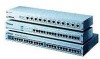
About this Guide This guide provides instructions for instal-ling all of the products described below. These D-Link® Ethernet Hubs are all Plug and Play compliant for easy installation. DE812TP+ DE-816TP - D-Link DE-824TP | User Guide - Page 3
Rack Mounting The Ethernet Hub may stand alone, or may be mounted in a standard 19-inch equip-ment rack. Rack mounting produces an orderly installation when you have a number of related network devices. Use the six supplied screws to fasten the supplied mounting brackets to either end of the hub, - D-Link DE-824TP | User Guide - Page 4
subnet by connecting the subnet bus to a rear-panel connector of the Ethernet Hub (irrespective of any star-topology subnet that may also be supported by the Ethernet Hub's front-panel ports). In either case, the unused rear-panel connector always remains available to connect a second coaxial cable - D-Link DE-824TP | User Guide - Page 5
connector), and thus can only be connected to the hub through a coaxial cable. Station Connections with Twisted-Pair Cable Connect each station to the Ethernet Hub by means of a twisted-pair straight cable (10BaseT cable, Category 3, 4, or 5). Plug one RJ-45 connector into a front-panel port of the - D-Link DE-824TP | User Guide - Page 6
Hub-to-Hub Connections with Twisted-Pair Cable Hub-to-hub connection between Model DE812TP+ Ethernet Hubs requires a 10BaseT crossover cable. In making a hub-to-hub connection involving a Model DE-816TP or Model DE-824 Ethernet Hub, there is the alternative of using a straight cable. Internal - D-Link DE-824TP | User Guide - Page 7
" (tall) position, the Port 1 connector is wired " straight" to the supporting circuitry, and Port 1 is then identical with each of the twenty-three other of a straight cable to make a hub-to-hub connection. Below in this manual, the term " Uplink selected" will mean, as to the Model DE-824TP - D-Link DE-824TP | User Guide - Page 8
Uplink should be selected only for making a hubto-hub connection with a straight cable. When Uplink is selected at one end of a straight cable, Uplink must not be selected at other end of that cable. (If Uplink were selected at both ends of a straight cable, then the built-in crossovers of the two - D-Link DE-824TP | User Guide - Page 9
to twist a 50-ohm terminator onto the remaining open leg of the BNC T. Sometimes several Ethernet Hubs must be colocated to support a larger array of stations than can be handled by a single Ethernet Hub. Then it is useful to stack the Ethernet Hubs by joining their BNC - D-Link DE-824TP | User Guide - Page 10
AUI cable between the transceiver's AUI connector and the AUI connector on the rear panel of the Ethernet Hub. Connecting Power For compatibility with electric service in most areas of the world, the Ethernet Hub's power supply automatically adjusts to line power in the range 100 - 250 VAC and 50 - D-Link DE-824TP | User Guide - Page 11
receptacle on the rear panel of the Ethernet Hub. Plug the other end of the power cord into an electric service outlet. Turn on power to the Ethernet Hub by switching its rear-panel power switch to the on position. LED Indicators LED indicators are located - D-Link DE-824TP | User Guide - Page 12
green (Receive state) indicates that the port is receiving data from its partner device. If the port is connected but the Link/Rx LED is dark, check whether (1) the Ethernet Hub and the partner device both have power, (2) the port's cable is firmly seated in its connectors in the Ethernet Hub and in - D-Link DE-824TP | User Guide - Page 13
Specifications Data transfer rate: 10 Mbps Protocol: CSMA/CD Topologies: Star, Bus EMI Certification: DE-812TP+ and DE-824TP: FCC Class A, VCCI I, CE A DE-816TP: FCC Class B, VCCI II, CE B AC power: 100 - 250 V, 50 - 60 Hz Power consumption: DE-812TP+: DE-816TP: DE-824TP: 18 W 18 W 20W - D-Link DE-824TP | User Guide - Page 14
Power cord: Type 1 (US) or Type 2 (Europe) per purchase order Type 1 Type 2 Plug Rating 125V, 7A Cord Rating Length Safety Standard 125V, 7A 1830mm (6ft) UL, CSA 250V, 10A 250V, 10A 1830mm (6ft) VDE
-
 1
1 -
 2
2 -
 3
3 -
 4
4 -
 5
5 -
 6
6 -
 7
7 -
8
-
9
-
10
-
11
-
12
-
13
-
14
 |
 |

Table of Contents
About this Guide
.............................................
1
Rack Mounting
................................................
3
Installing Network Cables
...............................
4
Station Connections with
Twisted-Pair Cable
.......................................
5
Hub-to-Hub Connections with
Twisted-Pair Cable
.......................................
6
Thin Coaxial Cable Connections
..................
8
Thick Coaxial Cable Connections
..............
10
Connecting Power
.........................................
10
LED Indicators
..............................................
11
Specifications
................................................
13