D-Link 130W Product Manual
D-Link 130W Manual
 |
View all D-Link 130W manuals
Add to My Manuals
Save this manual to your list of manuals |
D-Link 130W manual content summary:
- D-Link 130W | Product Manual - Page 1
Version 1.02 | 10/25/2023 1 - D-Link 130W | Product Manual - Page 2
. This equipment generates, uses, and can radiate radio frequency energy and, if not installed and used in accordance with this user's guide, may cause harmful interference to radio communications. Operation of this equipment in a residential area is likely to cause harmful interference in which - D-Link 130W | Product Manual - Page 3
DSS-200G MP/MPP Series Switch Web UI Reference Guide Table of Contents 1. Introduction ...1 Audience ...1 Standard Mode and Surveillance Mode...1 Other Documentation ...2 Conventions ...2 Notes, Notices, and Cautions ...2 2. Product Introduction ...3 DSS-200G-10MP ...4 Front Panel ...4 Rear - D-Link 130W | Product Manual - Page 4
DSS-200G MP/MPP Series Switch Web UI Reference Guide User Account Settings ...43 SNMP...44 SNMP Community Table Settings ...45 HTTP/HTTPS...47 D-Link Discovery Protocol ...47 Layer 2 Features ...49 FDB ...49 VLAN...52 - D-Link 130W | Product Manual - Page 5
DSS-200G MP/MPP Series Switch Web UI Reference Guide Enabling and Disabling PoE ...103 Device Information ...104 Port VLAN...129 Quality of Service (QoS) ...129 Security ...129 Management ...129 Power Saving...129 Surge Protection ...129 8. Appendix C -Rack Mount Instructions ...130 9. Appendix D - D-Link 130W | Product Manual - Page 6
based on the software release 1.00. The commands listed here are the subset of commands that are supported by the DSS-200G MP/MPP Series switch. Audience This reference manual is intended for network administrators and other IT networking professionals responsible for managing the switch by using - D-Link 130W | Product Manual - Page 7
manual for more information. For more information, please refer to the Web UI Interface Guide for the appropriate Web UI mode. Other Documentation The documents below are a further source of information in regard to configuring and troubleshooting problem. CAUTION: A caution indicates a potential for - D-Link 130W | Product Manual - Page 8
MP/MPP series Switch User Manual 2. Product Introduction TheDSS-200G MP/MPP series Surveillance Switch is a PoE switch with ONVIF support. This allows it to recognize ONVIF devices and integrate seamlessly with your surveillance network. Various power budgets support, including the high PoE (90 - D-Link 130W | Product Manual - Page 9
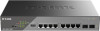
D-Link DSS-200G MP/MPP series Switch User Manual DSS-200G-10MP 8 x 10/100/1000 Mbps PoE ports + 2 x 100/1000 Mbps SFP surveillance switch Front Panel Figure 2-1 DSS-200G-10MP Front Panel Mode Button: - D-Link 130W | Product Manual - Page 10
D-Link DSS-200G MP/MPP series Switch User Manual The power LED has two states to indicate the Switch power status. Green The Switch is powered on using normal power supply. Off The Switch - D-Link 130W | Product Manual - Page 11
D-Link DSS-200G MP/MPP series Switch User Manual Solid Green Flashing Green An active link operating at 1000 Mbps on the port. The port is transmitting data at 1000 Mbps. PoE LED (Ports 1-8): - D-Link 130W | Product Manual - Page 12
Rear Panel D-Link DSS-200G MP/MPP series Switch User Manual Figure 2-2 DSS-200G-10MP Rear Panel Power: Connect the supplied AC power cable to this port. CAUTION: The SFP ports should use UL listed Optical - D-Link 130W | Product Manual - Page 13
D-Link DSS-200G MP/MPP series Switch User Manual Reset: The Reset button has 3 modes: Reset Mode Description Reboot Press the reset button and hold it for 1~5 seconds to reboot the device. Reset to - D-Link 130W | Product Manual - Page 14
D-Link DSS-200G MP/MPP series Switch User Manual Ports 1-8 comply with 802.3at and can supply up to 90 W power to the powered devices (PD). The Port LED can be switched between the - D-Link 130W | Product Manual - Page 15
LED QoS Extend Isolation PD-Alive STP D-Link DSS-200G MP/MPP series Switch User Manual Description If the QoS switch is enabled, incoming packets of the controlled ports (ports 1-24) are forwarded according to the port priority based on the - D-Link 130W | Product Manual - Page 16
D-Link DSS-200G MP/MPP series Switch User Manual DSS-200G-28MP 24 x 10/100/1000 Mbps PoE ports + 4 x 1000BASE-T/SFP Combo ports surveillance switch Front Panel Figure 2-5 DSS-200G-28MP Front Panel Mode - D-Link 130W | Product Manual - Page 17
D-Link DSS-200G MP/MPP series Switch User Manual Power LED: The power LED has two states to indicate the Switch power status. Green The Switch is powered on using normal power supply. Off - D-Link 130W | Product Manual - Page 18
D-Link DSS-200G MP/MPP series Switch User Manual Solid Green Flashing Green An active link operating at 1000 Mbps on the port. The port is transmitting data at 1000 Mbps. PoE LED (Ports 1- - D-Link 130W | Product Manual - Page 19
Rear Panel D-Link DSS-200G MP/MPP series Switch User Manual Figure 2-6 DSS-200G-28MP Rear Panel Power: Connect the supplied AC power cable to this port. CAUTION: The SFP ports should use UL listed Optical - D-Link 130W | Product Manual - Page 20
D-Link DSS-200G MP/MPP series Switch User Manual DSS-200G-28MPP 24 x 10/100/1000 Mbps PoE ports + 4 x 1000BASE-T/SFP Combo ports surveillance switch Front Panel Figure 2-7 DSS-200G-28MPP Front Panel Mode - D-Link 130W | Product Manual - Page 21
D-Link DSS-200G MP/MPP series Switch User Manual overload, and PoE power short circuit. The Alarm port on the back can also be connected to signify such events. Power LED: The power LED - D-Link 130W | Product Manual - Page 22
D-Link DSS-200G MP/MPP series Switch User Manual Solid Orange An active link operating at 100 Mbps on the port. Flashing Orange The port is transmitting data at 100 Mbps. Off There is - D-Link 130W | Product Manual - Page 23
D-Link DSS-200G MP/MPP series Switch User Manual Rear Panel Figure 2-8 DSS-200G-28MPP Rear Panel Power: Connect the supplied AC power cable to this port. CAUTION: The SFP ports should use UL - D-Link 130W | Product Manual - Page 24
DSS-200G MP/MPP series Switch User Manual 3. Hardware Installation This chapter provides unpacking Four rubber feet • Rackmount kit • One accessory kit for a ground screw • Quick Installation Guide Step2: Switch Installation For safe switch installation and operation, it is recommended that you: • - D-Link 130W | Product Manual - Page 25
D-Link DSS-200G MP/MPP series Switch User Manual CAUTION: Ensure the power cable is disconnected before Figure 3-3 Mount the switch in the rack or chassis Please be aware of following safety Instructions when installing: A) Elevated Operating Ambient - If installed in a closed or multi-unit rack - D-Link 130W | Product Manual - Page 26
D-Link DSS-200G MP/MPP series Switch User Manual Step 3: Plugging in the AC Power Cord Users may now connect the AC power cord into the rear of the switch and to an electrical - D-Link 130W | Product Manual - Page 27
D-Link DSS-200G MP/MPP series Switch User Manual Figure 3-5 Ground cable, screw and #8 terminal lug rings Cable The DSS-200G MP/MPP Series switches support the IEEE 802.3af and 802.3at Power over Ethernet (PoE) standards. The DSS-200G MPP Series also support the IEEE 802.3bt standard. The ports - D-Link 130W | Product Manual - Page 28
D-Link DSS-200G MP/MPP series Switch User Manual Class Maximum power used by PD Class Max power supplied by PSE 0 12.95W 0 16.2W 1 3.84W -200G-28MP DSS-200G-10MP (ports 1-8) / DSS-200G-28MP (ports 1-24): These ports support 802.3af/at to provide a maximum of 15 W or 30 W power supply to the - D-Link 130W | Product Manual - Page 29
-200G MP/MPP series Switch User Manual PDs. Whereas Ports 9-24 of DSS-200G-28MPP support 802.3af/at to provide 15 W or 30 W power supply to the connected PDs. In addition, DSS-200G-10MPP (ports 1-8) and DSS-200G-28MPP (ports 1-8) can also be configured to support PoE up to a maximum of 20 - D-Link 130W | Product Manual - Page 30
Link DSS-200G MP/MPP series Switch User Manual 4. Web-based Switch Configuration Management Options Connecting based Management The switch can be managed with an SNMP-compatible console program. The switch supports SNMP version 1.0, and version 2c. The SNMP agent decodes the incoming SNMP messages - D-Link 130W | Product Manual - Page 31
D-Link DSS-200G MP/MPP series Switch User Manual Logging onto the Web User Interface To access the Web UI, simply open a web browser and enter the switch's default IP address into the address - D-Link 130W | Product Manual - Page 32
D-Link DSS-200G MP/MPP series Switch User Manual Smart Wizard The Smart Wizard is a configuration continue the Smart Wizard in Surveillance Mode. Please refer to the Standard Mode Web UI Reference Guide for more information on Standard Mode. Tick the Ignore the wizard next time option to skip - D-Link 130W | Product Manual - Page 33
Information window The fields that can be configured are described below: Parameter Static DHCP IP Address Netmask Gateway Description Select this option to manually configure and use IP address settings on this switch. Select this option to obtain IP address settings from a DHCP server. Enter the - D-Link 130W | Product Manual - Page 34
D-Link DSS-200G MP/MPP series Switch User Manual Click the Exit button to discard the changes made, exit the Smart Wizard, and continue to the Standard Mode Web UI. Click the Next button - D-Link 130W | Product Manual - Page 35
D-Link DSS-200G MP/MPP series Switch User Manual Web User Interface - Standard Mode By clicking the Exit button in the Smart Wizard, you will enter the Web-based Management interface. Areas of the - D-Link 130W | Product Manual - Page 36
D-Link DSS-200G MP/MPP series Switch User Manual Figure 4-6 Devie Info System System Information Settings Port Configuration PoE System Log Time Time Range System Information Settings System Information The user can enter a System - D-Link 130W | Product Manual - Page 37
Parameter Get IP From IP Address Mask Gateway DHCP Retry Time(5-120) Description Select DHCP to automatically obtain an IP address. Select Static to manually configure the IP address settings. BOOTP allows the switch to get an IP configuration using the BOOTP protocol. If Static is selected, enter - D-Link 130W | Product Manual - Page 38
series Switch User Manual Port Configuration Port Settings This window is used to view and configure the switch's port settings. To view the following window, click System > Port Configuration > Port Settings, as shown below: Figure 4-10 Port Settings window Note: Ports are that support PoE Extent - D-Link 130W | Product Manual - Page 39
D-Link DSS-200G MP/MPP series Switch User Manual Port Status This window is used to view switch port Jumbo Frame size and settings. The switch supports jumbo frames. Jumbo frames are Ethernet frames with more than 1,518 bytes of payload. The switch supports jumbo frames with a maximum frame size of - D-Link 130W | Product Manual - Page 40
D-Link DSS-200G MP/MPP series Switch User Manual PoE PoE System This window is used to configure the PoE system and display the detailed power information and PoE Trap parameters for PoE modules. - D-Link 130W | Product Manual - Page 41
switch failed to supply power to the IEEE 802.3at/bt PD (Powered Device): 1. Check if the PD connected to the port supports the IEEE 802.3at/bt standard. 2. Manually configure the corresponding port's power limit value to 30, 60 or 90 Watts according to the port's PoE capability. PD Alive This - D-Link 130W | Product Manual - Page 42
D-Link DSS-200G MP/MPP series Switch User Manual Figure 4-15 PD Alive Configuration window The fields that can be configured are described below: Parameter Description From Port / To Port Select the appropriate port - D-Link 130W | Product Manual - Page 43
D-Link DSS-200G MP/MPP series Switch User Manual System Log System Log Settings This window is used to view and configure the system's log settings. To view the following window, click System > System - D-Link 130W | Product Manual - Page 44
D-Link DSS-200G MP/MPP series Switch User Manual Host IPv4 Address Enter the system log server's IPv4 - The lowest level of a device warning. The device is functioning, but an operational problem has occurred. Informational - Provides device information. All - Displays all levels of system logs - D-Link 130W | Product Manual - Page 45
is a protocol for system clock synchronization through the Internet. Clock Settings This window is used to configure the time settings for the switch manually. To view the following window, click System > Time > Clock Settings, as shown below: Figure 4-19 Clock Settings window The fields that can - D-Link 130W | Product Manual - Page 46
D-Link DSS-200G MP/MPP series Switch User Manual Summer Time State Time Zone Select the summer time setting. Options to choose from are Disabled, and Date Setting. Disabled - Select to disable the summer - D-Link 130W | Product Manual - Page 47
provide clock services. IPv4 Address Enter the IP address of the SNTP server which provides the clock synchronization. Click the Apply button to add the SNTP server. Time Range This window is used to view and configure the time range settings. The maximum number of time profiles supported by the - D-Link 130W | Product Manual - Page 48
D-Link DSS-200G MP/MPP series Switch User Manual Management User Account Settings SNMP HTTP/HTTPS D-Link Discovery Protocol User Account Settings This window is used to configure the user accounts. The active user - D-Link 130W | Product Manual - Page 49
D-Link DSS-200G MP/MPP series Switch User Manual SNMP Simple Network Management Protocol (SNMP) is an OSI for proper operation, monitor performance and detect potential problems in the switch, switch group or network. Managed devices that support SNMP include software (referred to as an agent), - D-Link 130W | Product Manual - Page 50
D-Link DSS-200G MP/MPP series Switch User Manual SNMP Global Settings This window is used to configure the SNMP global settings and trap settings. To view the following window, click Management > SNMP > SNMP - D-Link 130W | Product Manual - Page 51
D-Link DSS-200G MP/MPP series Switch User Manual Figure 4-25 SNMP Community Table Settings window The fields that can be configured are described below: Parameter Access Right Community Name Description Select the access - D-Link 130W | Product Manual - Page 52
D-Link DSS-200G MP/MPP series Switch User Manual Host IPv4 Address Enter the IPv4 address of the SNMP notification host. User-based Security Model Select the security model here. Options to choose from - D-Link 130W | Product Manual - Page 53
D-Link DSS-200G MP/MPP series Switch User Manual Figure 4-28 D-Link Discovery Protocol window The fields that can be configured for D-Link Discovery Protocol are described below: Parameter Description D-Link Discovery Protocol Select - D-Link 130W | Product Manual - Page 54
D-Link DSS-200G MP/MPP series Switch User Manual Layer 2 Features FDB VLAN Spanning Tree Loopback Detection Link Aggregation L2 Multicast Control LLDP FDB Static FDB Unicast Static FDB This window is used to - D-Link 130W | Product Manual - Page 55
D-Link DSS-200G MP/MPP series Switch User Manual Figure 4-30 Multicast Static FDB window The fields that can be configured are described below: Parameter From Port / To Port VID MAC Address Description Select - D-Link 130W | Product Manual - Page 56
D-Link DSS-200G MP/MPP series Switch User Manual Figure 4-32 MAC Address Table Settings (MAC Address Learning) window The fields that can be configured are described below: Parameter From Port / To Port State - D-Link 130W | Product Manual - Page 57
D-Link DSS-200G MP/MPP series Switch User Manual VLAN VLAN Configuration Wizard This window is the VLAN configuration wizard. To view the following window, click L2 Features > VLAN > VLAN Configuration Wizard, as shown - D-Link 130W | Product Manual - Page 58
D-Link DSS-200G MP/MPP series Switch User Manual 802.1Q VLAN This window is used to view and configure the VLAN settings on this switch. To view the following window, click L2 Features > - D-Link 130W | Product Manual - Page 59
D-Link DSS-200G MP/MPP series Switch User Manual Figure 4-38 VLAN Interface Information window More detailed information about the VLAN of the specific interface is displayed. Click the Back button to return to - D-Link 130W | Product Manual - Page 60
D-Link DSS-200G MP/MPP series Switch User Manual Parameter VLAN Mode Acceptable Frame Ingress Checking VID Action Allowed VLAN Range From Port / To Port Description Select the VLAN mode option here. Options to - D-Link 130W | Product Manual - Page 61
D-Link DSS-200G MP/MPP series Switch User Manual Allowed VLAN Range From Port / To Port If the Action chosen is Add or Remove, enter the allowed VLAN range information here. Select the appropriate - D-Link 130W | Product Manual - Page 62
D-Link DSS-200G MP/MPP series Switch User Manual VLAN State Select this option to enable or disable the Port-based VLAN function. Click the Apply button to accept the changes made. When setting - D-Link 130W | Product Manual - Page 63
D-Link DSS-200G MP/MPP series Switch User Manual Management VLAN State VID Select this option to enable or disable the Management VLAN function. VLAN VID is a unique number (between 1 and 4094) that identifies a - D-Link 130W | Product Manual - Page 64
D-Link DSS-200G MP/MPP series Switch User Manual Aging Time Enter the aging time of surveillance VLAN. The range is from 1 to 65535 minutes. The default value is 720 minutes. The aging time - D-Link 130W | Product Manual - Page 65
D-Link DSS-200G MP/MPP series Switch User Manual Figure 4-28 MAC Settings and Surveillance Device(Auto an IP phone call will be deteriorated if the data is unevenly sent, the quality of service (QoS) for voice traffic shall be configured to ensure the transmission priority of voice packet is - D-Link 130W | Product Manual - Page 66
D-Link DSS-200G MP/MPP series Switch User Manual Voice VLAN Port This window is used to configure the user- . Choose the Voice VLAN mode for the port. This can be Auto untagged, Auto Tagged, or Manual configured. Click the Apply button to accept the changes made. Voice VLAN OUI This window is used - D-Link 130W | Product Manual - Page 67
D-Link DSS-200G MP/MPP series Switch User Manual OUI Address Mask Description Enter the OUI MAC address. Enter the OUI MAC address matching bitmask. Enter the description for the user-defined OUI with a - D-Link 130W | Product Manual - Page 68
D-Link DSS-200G MP/MPP series Switch User Manual Spanning Tree This switch supports two versions of the Spanning Tree Protocol: 802.1D-1998 STP, 802.1D-2004 Rapid STP. 802.1D-1998 STP will be familiar to most - D-Link 130W | Product Manual - Page 69
D-Link DSS-200G MP/MPP series Switch User Manual STP Global Settings This window is used to view and configure the STP global settings. To view the following window, click L2 Features > Spanning Tree > - D-Link 130W | Product Manual - Page 70
D-Link DSS-200G MP/MPP series Switch User Manual Figure 4-35 STP Port Settings window The fields that can be configured are described below: Parameter From Port / To Port State Port Fast Description Select - D-Link 130W | Product Manual - Page 71
D-Link DSS-200G MP/MPP series Switch User Manual Figure 4-36 Loopback Detection window The fields that can be configured for Loopback Detection Global Settings are described below: Parameter Loopback Detection State Trap State - D-Link 130W | Product Manual - Page 72
D-Link DSS-200G MP/MPP series Switch User Manual State Select this option to enable or disable the state of the port. Click the Apply button to accept the changes made. Note: If Spanning - D-Link 130W | Product Manual - Page 73
D-Link DSS-200G MP/MPP series Switch User Manual All of the ports in the group must be members of the same VLAN, and their STP status, static multicast, traffic control; traffic segmentation and - D-Link 130W | Product Manual - Page 74
D-Link DSS-200G MP/MPP series Switch User Manual Parameter From Port / To Port Group ID at least one of the participating devices must designate LACP ports as active. Both devices must support LACP. Passive - LACP ports that are designated as passive cannot initially send LACP control frames. - D-Link 130W | Product Manual - Page 75
D-Link DSS-200G MP/MPP series Switch User Manual L2 Multicast Control IGMP Snooping Internet Group Management Protocol (IGMP) snooping allows the switch to recognize IGMP queries and reports sent between network stations or - D-Link 130W | Product Manual - Page 76
D-Link DSS-200G MP/MPP series Switch User Manual IGMP Snooping Groups Settings This window is used to configure and view the IGMP snooping static group, and view IGMP snooping group. To view the - D-Link 130W | Product Manual - Page 77
D-Link DSS-200G MP/MPP series Switch User Manual The fields that can be configured for IGMP Snooping Static Groups Settings are described below: Parameter From Port / To Port State Description Select the appropriate - D-Link 130W | Product Manual - Page 78
D-Link DSS-200G MP/MPP series Switch User Manual selecting the Forward Unregistered option, registered multicast packets will be forwarded based on the forwarding table and all unregistered multicast packets will be flooded based - D-Link 130W | Product Manual - Page 79
D-Link DSS-200G MP/MPP series Switch User Manual LLDP LLDP Global Settings LLDP (Link Layer Discovery Protocol) provides IEEE 802.1AB standards-based method for switches to advertise themselves to neighbor devices, as - D-Link 130W | Product Manual - Page 80
D-Link DSS-200G MP/MPP series Switch User Manual QoS 802.1p Priority Port Rate Limiting 802.1p the weighted round-robin (WRR) algorithm to handle packets in an even distribution in priority classes of service. Click the Apply button to accept the changes made. The fields that can be configured 802. - D-Link 130W | Product Manual - Page 81
D-Link DSS-200G MP/MPP series Switch User Manual Figure 4-49 802.1p Priority Settings (DSCP) window The fields that can be configured DSCP Table are described below: Parameter From Port / To Port Scheduler - D-Link 130W | Product Manual - Page 82
D-Link DSS-200G MP/MPP series Switch User Manual When Direction is Output, this drop-down menu allows you to select data rate from 16Kbps to 512Mbps. Click the Apply button to accept the - D-Link 130W | Product Manual - Page 83
D-Link DSS-200G MP/MPP series Switch User Manual The fields that can be configured are described below made. DoS Attack Prevention Settings This window is used to view and configure the Denial-of-Service (DoS) attack prevention settings. The following well-known DoS types which can be detected by - D-Link 130W | Product Manual - Page 84
D-Link DSS-200G MP/MPP series Switch User Manual • TCP SYN Src Port Less 1024: This type of attack involves port scanning by using specific packets which contain source port 0 to 1023 and SYN - D-Link 130W | Product Manual - Page 85
D-Link DSS-200G MP/MPP series Switch User Manual The fields that can be configured for Zone Defense Settings are described below: Parameter Zone Defense State Description Select to enable or disable the Zone - D-Link 130W | Product Manual - Page 86
200G MP/MPP series Switch User Manual OAM Cable Diagnostics The cable diagnostics feature is designed primarily for administrators or customer service representatives to verify and test copper Cable Diagnostics feature is only supported on the copper ports on all DSS-200G MP/MPP Series switches. 81 - D-Link 130W | Product Manual - Page 87
D-Link DSS-200G MP/MPP series Switch User Manual Monitoring Statistics Mirror Settings Statistics Port Counters This window is used the first port. This is useful for network monitoring and troubleshooting purposes. To view the following window, click Monitoring > Mirror Settings, as shown below: - D-Link 130W | Product Manual - Page 88
D-Link DSS-200G MP/MPP series Switch User Manual Figure 4-59 Mirror Settings window The fields that can be configured for Mirror Settings are described below: Parameter Destination Source Description Select one destination port - D-Link 130W | Product Manual - Page 89
D-Link DSS-200G MP/MPP series Switch User Manual Green Power Saving EEE Power Saving This window is used to configure the power saving settings of the switch. To view the following window, click - D-Link 130W | Product Manual - Page 90
D-Link DSS-200G MP/MPP series Switch User Manual Click the Delete button to remove the specified entry. After clicking the Power Saving Shutdown Settings tab, the following page will appear. Figure 4-61 Power - D-Link 130W | Product Manual - Page 91
D-Link DSS-200G MP/MPP series Switch User Manual The fields that can be configured are described below: Parameter From Port / To Port State . Click the Apply button to accept the changes made. Note: The EEE feature is only supported on the copper ports on all DSS-200G MP/MPP Series switches. 86 - D-Link 130W | Product Manual - Page 92
physical security products. The DSS-200G MP/MPP Series support the ONVIF protocol, and its settings can be configured below. The on the switch and can be manually configured to be a VLAN created in the VLAN section of this document. This is the VLAN Class of Service and can be set to a value - D-Link 130W | Product Manual - Page 93
D-Link DSS-200G MP/MPP series Switch User Manual IP-Camera Information The IP-Camera Information page shows the devices that have been discovered through ONVIF. These are ONVIF-compatible devices that have been - D-Link 130W | Product Manual - Page 94
D-Link DSS-200G MP/MPP series Switch User Manual Dip Switch Dip Status Extend (250M@10Mbps) Dip power through a 250meter network cable (20 watts with Cat 5e cable or above). Note that the ports support this PoE Extend feature are ports 1-4 of DSS-200G-10MP/10MPP and ports 1-8 of DSS-200G28MP/28MPP. - D-Link 130W | Product Manual - Page 95
D-Link DSS-200G MP/MPP series Switch User Manual Extend This window is to view the status of the port Extend State for the PoE function. To view the following window, click Dip Switch > - D-Link 130W | Product Manual - Page 96
firmware image as the active image to use upon the next system start up. Note: Changing the firmware only happens after the switch has been manually rebooted. In order to boot with the newly selected firmware, make sure that the switch is rebooted. Firmware Upgrade Note: When upgrading the firmware - D-Link 130W | Product Manual - Page 97
D-Link DSS-200G MP/MPP series Switch User Manual Firmware Upgrade from HTTP This window is used to initiate a firmware upgrade from a local PC using HTTP. To view the following window, click Tools > Firmware - D-Link 130W | Product Manual - Page 98
D-Link DSS-200G MP/MPP series Switch User Manual Configuration Restore & Backup Configuration Restore from HTTP This window is used to initiate a configuration restore from a local PC using HTTP. Note: If the switch is - D-Link 130W | Product Manual - Page 99
D-Link DSS-200G MP/MPP series Switch User Manual Click the Restore button to initiate the configuration restore. Click Effective immediately (running-config) to have the uploaded configuration loaded immediately. Click Take effect after - D-Link 130W | Product Manual - Page 100
D-Link DSS-200G MP/MPP series Switch User Manual Log Backup Log Backup to HTTP This window is used to initiate a system log backup to a local PC using HTTP. To view the following window, - D-Link 130W | Product Manual - Page 101
D-Link DSS-200G MP/MPP series Switch User Manual Ping Ping is a small program that sends ICMP Echo packets to the IP address you specify. The destination node then responds to or "echoes" the - D-Link 130W | Product Manual - Page 102
D-Link DSS-200G MP/MPP series Switch User Manual Figure 4-51 Reset window Select The Switch will be reset to its factory defaults including IP address and stacking information, and then will save and - D-Link 130W | Product Manual - Page 103
D-Link DSS-200G MP/MPP series Switch User Manual 5. Surveillance Web User Interface - Surveillance Mode When you complete the Surveillance Mode Smart Wizard you will be presented with the following screen: Figure 5-1 Congratulations window - D-Link 130W | Product Manual - Page 104
D-Link DSS-200G MP/MPP series Switch User Manual Areas of the User Interface The figure below shows the user interface. Two distinct areas divide the user interface, as described in the table. AREA 3 - D-Link 130W | Product Manual - Page 105
D-Link DSS-200G MP/MPP series Switch User Manual The Surveillance Overview page loads automatically when you log-in to the switch and contains two tabs; Surveillance Topology and Device Information. To return to - D-Link 130W | Product Manual - Page 106
200G MP/MPP series Switch User Manual D-LINK IPC Discovered by Surveillance VLAN but not support ONVIF protocol. The total number connecting the Powered Device (PD) and enabling 60/90 W PoE, make sure it supports IEEE802.3bt, as otherwise it will become damaged. See below for more information on - D-Link 130W | Product Manual - Page 107
D-Link DSS-200G MP/MPP series Switch User Manual Multiple ONVIF IP cameras and one NVR discovered on this -party devices do not fully comply with the ONVIF standard. If you are having problems with surveillance devices not being detected, please check the ONVIF compatibility with the original - D-Link 130W | Product Manual - Page 108
D-Link DSS-200G MP/MPP series Switch User Manual The device is operational and is powered by PoE PoE CAUTION: Before connecting the Powered Device (PD) and enabling 60/90 W PoE, make sure it supports IEEE802.3bt, The power status of each port can be changed by clicking the power icon on each port - D-Link 130W | Product Manual - Page 109
D-Link DSS-200G MP/MPP series Switch User Manual Device Information This is the second tab on the Surveillance Overview page and is divided into 7 areas; a device information section, PoE utilization section, bandwidth utilization - D-Link 130W | Product Manual - Page 110
D-Link DSS-200G MP/MPP series Switch User Manual Port Information The Port Information section provides an overview of the port status for each port. This includes the total number of NVRs detected. The number of ports that have an unknown device connected that does not support ONVIF. 105 - D-Link 130W | Product Manual - Page 111
D-Link DSS-200G MP/MPP series Switch User Manual Hover-over each field to get more information about each value. A breakdown of each field is below: Icon Description The port number of the port. - D-Link 130W | Product Manual - Page 112
D-Link DSS-200G MP/MPP series Switch User Manual Group Details The Group Details page lists the devices connected to a specific port. Only devices that have been recognized as supporting ONVIF or NVRs will be displayed. To view the following window, click on the Port Information link in the - D-Link 130W | Product Manual - Page 113
D-Link DSS-200G MP/MPP series Switch User Manual IP-Camera Information The IP-Camera Information section provides information on each camera connected to the switch. It features the port number, device type, throughput, - D-Link 130W | Product Manual - Page 114
D-Link DSS-200G MP/MPP series Switch User Manual The PoE consumption of the port. This is listed as one negative integer and one positive integer. A negative value for PoE means that power is - D-Link 130W | Product Manual - Page 115
D-Link DSS-200G MP/MPP series Switch User Manual PoE Information The PoE Information section provides information on the PoE usage of each port. The port number, PoE status, health status, PoE budget and - D-Link 130W | Product Manual - Page 116
Manual The port number of the port. The PoE status for the port (PoE on or off). The maximum PoE power budget for this port. This can be 30 W, or 30 W/60 W/90 W if this port supports 4-pair PoE. The PoE state. If any fault is detected the icon changes to include a description of the problem - D-Link 130W | Product Manual - Page 117
D-Link DSS-200G MP/MPP series Switch User Manual PoE Scheduling PoE Scheduling is a feature which allows you to specify the amount of time that power is delivered to a PoE port. This can be - D-Link 130W | Product Manual - Page 118
D-Link DSS-200G MP/MPP series Switch User Manual Parameter From Port To Port Time Range Description The start port in the range that the PoE schedule will apply to. The end port in - D-Link 130W | Product Manual - Page 119
D-Link DSS-200G MP/MPP series Switch User Manual PD Alive This window is used to configure the PD Alive function for PDs connected to the PoE ports. The ping function via ICMP requests - D-Link 130W | Product Manual - Page 120
D-Link DSS-200G MP/MPP series Switch User Manual Click the Apply button to accept the changes made. Time Clock Settings SNTP Settings Clock Settings This sub-menu is used to configure the time - D-Link 130W | Product Manual - Page 121
D-Link DSS-200G MP/MPP series Switch User Manual Parameter Description Current Time Source Displays the current time source for the switch. SNTP State Set the SNTP state. Options are Enabled or Disabled. Pool - D-Link 130W | Product Manual - Page 122
D-Link DSS-200G MP/MPP series Switch User Manual Surveillance Settings The Surveillance Settings page is used to configure the settings for the Surveillance VLAN. This is a VLAN dedicated for IP camera and surveillance - D-Link 130W | Product Manual - Page 123
D-Link DSS-200G MP/MPP series Switch User Manual Parameter Host IPv4 Address Description Enter the IP address of the SNMP Network Management Server (NMS) which will receive SNMP Traps from this device. Click - D-Link 130W | Product Manual - Page 124
D-Link DSS-200G MP/MPP series Switch User Manual Surveillance Log The Surveillance Log consists of a list of Sys log messages that have been generated by the switch. Depending on whether a Sys log server - D-Link 130W | Product Manual - Page 125
D-Link DSS-200G MP/MPP series Switch User Manual Health Diagnostic The Health Diagnostic page is linked-to by the Port Information and PoE Information pages and displays an overview of the port status. - D-Link 130W | Product Manual - Page 126
image as the active image to use upon the next system start up. NOTE: Changing the firmware only takes effect after the switch has been manually rebooted. In order to boot with the newly selected firmware, make sure that the switch is rebooted. Firmware Upgrade NOTE: When upgrading the firmware on - D-Link 130W | Product Manual - Page 127
D-Link DSS-200G MP/MPP series Switch User Manual Parameter Description Source File Enter the source filename and path of the firmware file located on the local PC. Alternatively click the Browse button to - D-Link 130W | Product Manual - Page 128
D-Link DSS-200G MP/MPP series Switch User Manual Configuration Restore & Backup Configuration Restore from HTTP This window is used to initiate a configuration restore from a local PC using HTTP. NOTE: If the switch is - D-Link 130W | Product Manual - Page 129
D-Link DSS-200G MP/MPP series Switch User Manual To view the following window, click Tools >Reset, as shown below: Figure 5-21 Reset window Select The Switch will be reset to its factory defaults - D-Link 130W | Product Manual - Page 130
D-Link DSS-200G MP/MPP series Switch User Manual Help Help Click the Help button on the page for Help information. Figure 5-24 Help Window 125 - D-Link 130W | Product Manual - Page 131
D-Link DSS-200G MP/MPP series Switch User Manual 6. Appendix A - Ethernet Technology This chapter will describe the features an extension of IEEE 802.3 Ethernet utilizing the same packet structure, format, and support for CSMA/CD protocol, full duplex, and management objects, but with a tenfold - D-Link 130W | Product Manual - Page 132
D-Link DSS-200G MP/MPP series Switch User Manual The switch acts as a high-speed selective bridge between the individual segments. The switch, without interfering with any other segments, automatically forwards traffic that needs - D-Link 130W | Product Manual - Page 133
D-Link DSS-200G MP/MPP Series Switch User Manual 7. Appendix B - Technical Specifications Hardware Specifications Key Components only) -Supports Full/half-Duplex operations at 10/100Mbps - Supports Full-Duplex operation at 1000Mbps - Supports IEEE 802.3x Flow Control - Support Auto-Negotiation - D-Link 130W | Product Manual - Page 134
D-Link DSS-200G MP/MPP series Switch User Manual Operation Temperature: -5~50°C Storage Temperature: -40~70°C VLAN Auto Surveillance VLAN Voice VLAN: Asymmetric VLAN Quality of Service (QoS) 802.1p priority 8 queues Bandwidth Control Security All PoE ports support 6 KV surge protection 129 - D-Link 130W | Product Manual - Page 135
D-Link DSS-200G MP/MPP Series Switch User Manual 8. Appendix C -Rack Mount Instructions Safety Instructions - Rack Mount Instructions - The following or similar rack-mount instructions are included with the installation instructions: A) Elevated Operating Ambient - If installed in a closed or multi- - D-Link 130W | Product Manual - Page 136
D-LinkDSS-200G MP/MPP series Switch User Manual 9. Appendix D - Surveillance Mode Defaults Enabling Surveillance Mode activates the following settings: • Enables the Auto Surveillance VLAN • PD Alive disabled on all ports • Disables QoS • Enables D-
-
 1
1 -
 2
2 -
 3
3 -
 4
4 -
 5
5 -
 6
6 -
 7
7 -
8
-
9
-
10
-
11
-
12
-
13
-
14
-
15
-
16
-
17
-
18
-
19
-
20
-
21
-
22
-
23
-
24
-
25
-
26
-
27
-
28
-
29
-
30
-
31
-
32
-
33
-
34
-
35
-
36
-
37
-
38
-
39
-
40
-
41
-
42
-
43
-
44
-
45
-
46
-
47
-
48
-
49
-
50
-
51
-
52
-
53
-
54
-
55
-
56
-
57
-
58
-
59
-
60
-
61
-
62
-
63
-
64
-
65
-
66
-
67
-
68
-
69
-
70
-
71
-
72
-
73
-
74
-
75
-
76
-
77
-
78
-
79
-
80
-
81
-
82
-
83
-
84
-
85
-
86
-
87
-
88
-
89
-
90
-
91
-
92
-
93
-
94
-
95
-
96
-
97
-
98
-
99
-
100
-
101
-
102
-
103
-
104
-
105
-
106
-
107
-
108
-
109
-
110
-
111
-
112
-
113
-
114
-
115
-
116
-
117
-
118
-
119
-
120
-
121
-
122
-
123
-
124
-
125
-
126
-
127
-
128
-
129
-
130
-
131
-
132
-
133
-
134
-
135
-
136
 |
 |

1
Version 1.02 | 10/25/2023