Compaq 245161-B22 10000 Series Rack Reference Guide
Compaq 245161-B22 - 10642 42U Rack Shock Pallet Manual
 |
UPC - 720591208066
View all Compaq 245161-B22 manuals
Add to My Manuals
Save this manual to your list of manuals |
Compaq 245161-B22 manual content summary:
- Compaq 245161-B22 | 10000 Series Rack Reference Guide - Page 1
HP10000 Series Rack Reference Guide December 2002 (Second Edition) Part Number 258200-002 - Compaq 245161-B22 | 10000 Series Rack Reference Guide - Page 2
in this document is provided "as is" without warranty of any kind and is subject to change without notice. The warranties for HP products are set forth in the express limited warranty statements accompanying such products. Nothing herein should be construed as constituting an additional warranty - Compaq 245161-B22 | 10000 Series Rack Reference Guide - Page 3
in Text...ix Getting Help...x Technical Support ...x HP Website...x Authorized Reseller...xi Reader's Comments...xi Chapter 1 Overview 10000 Series Racks...1-2 Rack Options ...1-3 Delivery Considerations 1-5 Installation Overview...1-5 Installation Service...1-6 Chapter 2 Configuration Factors Rack - Compaq 245161-B22 | 10000 Series Rack Reference Guide - Page 4
the Component 4-18 Inserting the Component into the Rack 4-18 Attaching the Cable Management Arm 4-20 Routing the Cables 4-23 Rack Option Kits...4-26 iv HP 10000 Series Rack Reference Guide - Compaq 245161-B22 | 10000 Series Rack Reference Guide - Page 5
B Transportation Instructions Transportation Methods B-1 Air Transport...B-1 Land Transport ...B-2 Sea Transport ...B-2 Delivery Services...B-2 Inside Rack Delivery Service B-2 Expedited Rack Delivery Service B-3 Shipping/Delivery Considerations B-4 Index HP 10000 Series Rack Reference Guide v - Compaq 245161-B22 | 10000 Series Rack Reference Guide - Page 6
About This Guide This guide provides step-by-step instructions for installation, and reference information for operation for the HP 10000 Series the presence of hazardous energy circuits or electric shock hazards. Refer all servicing to qualified personnel. WARNING: To reduce the risk of injury from - Compaq 245161-B22 | 10000 Series Rack Reference Guide - Page 7
About This Guide This symbol indicates the presence of electric shock hazards. The area contains no user or field serviceable parts. Do not open for any reason. WARNING occupational health and safety requirements and guidelines for manual material handling. viii HP 10000 Series Rack Reference Guide - Compaq 245161-B22 | 10000 Series Rack Reference Guide - Page 8
extended for any reason. Symbols in Text These symbols may be found in the text of this guide. They have the following meanings. WARNING: Text set off in this manner indicates that failure to emphasize or supplement important points of the main text. HP 10000 Series Rack Reference Guide ix - Compaq 245161-B22 | 10000 Series Rack Reference Guide - Page 9
Getting Help If you have a problem and have exhausted the information in this guide, you can get further information and other help in the following locations. Technical Support In North America, call the HP Technical Support Phone Center at 1-800-652-6672. This service is available 24 hours a day - Compaq 245161-B22 | 10000 Series Rack Reference Guide - Page 10
reseller: • In the United States, call 1-800-345-1518. • In Canada, call 1-800-263-5868. • Elsewhere, see the HP website for locations and telephone numbers. Reader's Comments HP welcomes your comments on this guide. Please send your comments and suggestions by e-mail to ServerDocumentation - Compaq 245161-B22 | 10000 Series Rack Reference Guide - Page 11
and complexity, managing them has become a critical concern. By centralizing your equipment in a HP 10000 Series rack, the efficiency and accessibility of your system can be increased dramatically. For example, one U is 44.45 millimeters (1.75 inches) high. HP 10000 Series Rack Reference Guide 1-1 - Compaq 245161-B22 | 10000 Series Rack Reference Guide - Page 12
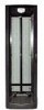
perforated front and split rear doors • Cable access panel on rear door • Perforated rack top with egress slot • Graphite metallic color Figure 1-1: 10000 Series racks 1-2 HP 10000 Series Rack Reference Guide - Compaq 245161-B22 | 10000 Series Rack Reference Guide - Page 13
a sampling of the many rack option kits available. For more information, visit the HP website at www.hp.com. Table 1-1: Rack Options Option Side Panels Rack Option Kit Stabilizer Rack Option Kit servers Routes and organizes cables within the rack continued HP 10000 Series Rack Reference Guide 1-3 - Compaq 245161-B22 | 10000 Series Rack Reference Guide - Page 14
information about these products, see the HP website at www.hp.com. Contact the nearest HP authorized reseller or service provider for information about ordering rack option kits. For the name of the nearest HP authorized reseller, see "About This Guide." 1-4 HP 10000 Series Rack Reference - Compaq 245161-B22 | 10000 Series Rack Reference Guide - Page 15
many delivery considerations available. For more information, visit the Best Practices web page at www.hp.com. When preparing to receive palletized racks, consider the following: • The dock door at System (UPS) units starting from the bottom of the rack. HP 10000 Series Rack Reference Guide 1-5 - Compaq 245161-B22 | 10000 Series Rack Reference Guide - Page 16
installed by qualified guaranteed service providers. This installation service covers the entire hardware installation sequence, from unpacking the components to routing cabling and running a test of the system. For more information on HP support, see "About This Guide." 1-6 HP 10000 Series Rack - Compaq 245161-B22 | 10000 Series Rack Reference Guide - Page 17
requirements, affect installation order and component placement in the rack. Rack Configuration Software To help you plan your rack configuration more efficiently, HP provides Rack Builder Online, the browser-based rack configuration tool. The latest version of the software is available at www - Compaq 245161-B22 | 10000 Series Rack Reference Guide - Page 18
rack configuration labeling and rack suite graphics for configurations that include multiple racks. • Third-Party Support-Allows you to define and add third-party products. If you are planning a new rack for installation and use of the software programs. 2-2 HP 10000 Series Rack Reference Guide - Compaq 245161-B22 | 10000 Series Rack Reference Guide - Page 19
is installed, do not exceed its output rating. Be sure to review the installation instructions provided with each component for important cautions and warnings. • PDUs-Install PDUs before installing unless you are using a rack-mountable flat panel monitor. HP 10000 Series Rack Reference Guide 2-3 - Compaq 245161-B22 | 10000 Series Rack Reference Guide - Page 20
-rated (CL2P) cable, please contact your local HP authorized reseller to obtain the following options: • 149363-B21-20-foot plenum cable • 149364-B21-40-foot plenum cable • Baying Option Kits-The Stabilizing Feet-A stand-alone rack requires stabilizing feet. 2-4 HP 10000 Series Rack Reference Guide - Compaq 245161-B22 | 10000 Series Rack Reference Guide - Page 21
At least 38 centimeters (15 inches) of clearance is needed around a power supply to facilitate servicing. Power Requirements WARNING: To reduce the risk of personal injury, fire, or damage to the equipment 80 percent of the branch circuit AC current rating. HP 10000 Series Rack Reference Guide 2-5 - Compaq 245161-B22 | 10000 Series Rack Reference Guide - Page 22
a grounded (earthed) power outlet that is easily accessible and located as close as possible to the equipment. The grounding plug is an important safety feature. 2-6 HP 10000 Series Rack Reference Guide - Compaq 245161-B22 | 10000 Series Rack Reference Guide - Page 23
-ventilated, climate-controlled environment. The HP Maximum Recommended Ambient Operating Temperature (TMRA Equipment Included HP rack-mountable servers HP rack-mountable options HP PDUs Other manufacturers increase the internal rack temperature beyond the HP specified maximum rating. • Make sure - Compaq 245161-B22 | 10000 Series Rack Reference Guide - Page 24
Configuration Factors Airflow Requirements HP rack-mountable products typically draw in cool air through the front and exhaust warm air out through in the airflow, which can adversely affect cooling within the rack. Cover these gaps with blanking panels. 2-8 HP 10000 Series Rack Reference Guide - Compaq 245161-B22 | 10000 Series Rack Reference Guide - Page 25
: • Required tools • Checking the hardware • Removing the rack doors • Removing the side panels • Stabilizing the rack - Standalone racks - Multiple racks • Server/Storage vs. switching configurations HP 10000 Series Rack Reference Guide 3-1 - Compaq 245161-B22 | 10000 Series Rack Reference Guide - Page 26
-powered screwdrivers. Checking the Hardware After unpacking the rack and its components, locate the HP Rack Kit Components List that was shipped with your rack. Verify that you received all installation. IMPORTANT: Retain the extra fasteners for future use. 3-2 HP 10000 Series Rack Reference Guide - Compaq 245161-B22 | 10000 Series Rack Reference Guide - Page 27
(1) and press the handle release button (2). The handle pops out. 2. Lift the handle up and out to open the door (3). 3 1 2 Figure 3-1: Opening the front door HP 10000 Series Rack Reference Guide 3-3 - Compaq 245161-B22 | 10000 Series Rack Reference Guide - Page 28
out and away from the rack (3). Store the door in an upright position, taking care to protect it from damage. 2 3 1 Figure 3-2: Removing the front door 3-4 HP 10000 Series Rack Reference Guide - Compaq 245161-B22 | 10000 Series Rack Reference Guide - Page 29
Preparing the Rack for Component Installation To remove the rack rear doors: 1. Rotate the handle to the right (1). 2. Pull the handle to open the doors (2). 1 2 Figure 3-3: Opening the rear doors HP 10000 Series Rack Reference Guide 3-5 - Compaq 245161-B22 | 10000 Series Rack Reference Guide - Page 30
and remove them from the rack (2). Store the doors in an upright position, taking care to protect them from damage. 2 1 1 Figure 3-4: Removing the rear doors 3-6 HP 10000 Series Rack Reference Guide - Compaq 245161-B22 | 10000 Series Rack Reference Guide - Page 31
side panel from the rack (3). Store the panels in an upright position, taking care to protect them from damage. 2 1 3 Figure 3-5: Removing the rack side panels Instructions for replacing the side panels are given in the Side Panel Rack Option Kit Installation - Compaq 245161-B22 | 10000 Series Rack Reference Guide - Page 32
follow these instructions carefully and heed all cautions and warnings throughout the installation instructions. Standalone Racks -feet bases provided with your rack. These feet support the rack and help compensate for uneven surfaces. support the weight of the rack and may become damaged if relied on - Compaq 245161-B22 | 10000 Series Rack Reference Guide - Page 33
Installation Stabilizing Feet WARNING: To reduce the risk of personal injury, you must attach HP Series rack stabilizing feet to all standalone (non-bayed) racks. The Stabilizer Rack Option rack. Figure 3-6: Full-size stabilizing feet attached (top view) HP 10000 Series Rack Reference Guide 3-9 - Compaq 245161-B22 | 10000 Series Rack Reference Guide - Page 34
/storage configuration with internal mounting rails that are front-justified, providing the customer greater room in the rear of the rack for cable management. 3-10 HP 10000 Series Rack Reference Guide - Compaq 245161-B22 | 10000 Series Rack Reference Guide - Page 35
the rails • Preparing the component • Installing the component - Inserting the component into the rack - Attaching the cable management arm - Attaching the cables - Routing the cables HP 10000 Series Rack Reference Guide 4-1 - Compaq 245161-B22 | 10000 Series Rack Reference Guide - Page 36
internal rack temperature beyond the specified maximum rating. • Be sure that the option equipment installed does not exceed the Manufacturer's Maximum Recommended Ambient Operating Temperature. 4-2 HP 10000 Series Rack Reference Guide - Compaq 245161-B22 | 10000 Series Rack Reference Guide - Page 37
Components Observe the general guidelines when loading your components: • For detailed instructions on installing a specific component or third-party hardware, see the user the rear of the rack to provide adequate access for installation and service. HP 10000 Series Rack Reference Guide 4-3 - Compaq 245161-B22 | 10000 Series Rack Reference Guide - Page 38
to the component. 7. Attach any cables and power cords, being sure that you adhere to all cautions and warnings contained in the individual component installation instructions. 8. Remove the cable access panel and route the cables. 4-4 HP 10000 Series Rack Reference Guide - Compaq 245161-B22 | 10000 Series Rack Reference Guide - Page 39
the back of the template to mark the attachment points for rack-mounting brackets, rails, components, or cage nuts on the back of the rack. HP 10000 Series Rack Reference Guide 4-5 - Compaq 245161-B22 | 10000 Series Rack Reference Guide - Page 40
cage nut. 3. Use the insertion tool to pull the cage nut through the hole until the top lip snaps into position. Figure 4-2: Inserting cage nuts 4-6 HP 10000 Series Rack Reference Guide - Compaq 245161-B22 | 10000 Series Rack Reference Guide - Page 41
Installing the Rails IMPORTANT: The installation instructions below are for standard installations. For specific installation instructions, please refer to the documentation the wing nuts slightly to stabilize the rail-mounting brackets during installation. HP 10000 Series Rack Reference Guide 4-7 - Compaq 245161-B22 | 10000 Series Rack Reference Guide - Page 42
fixed rail to the front of the rack. NOTE: After installing your components, insert at least one more screw into each adjustable rail for additional support. Figure 4-4: Securing the adjustable fixed rail to the front of the rack - Compaq 245161-B22 | 10000 Series Rack Reference Guide - Page 43
rails to the rear of the rack. NOTE: After installing your components, insert at least one more screw into each adjustable rail for additional support. Figure 4-5: Securing the adjustable fixed rail to the rear of the rack 3. Retighten the wing nuts on the adjustable rails. The adjustable fixed - Compaq 245161-B22 | 10000 Series Rack Reference Guide - Page 44
the component rail to the component before you insert the unit into the rack. 2 1 Figure 4-6: Removing the component rail from the sliding rail assembly 4-10 HP 10000 Series Rack Reference Guide - Compaq 245161-B22 | 10000 Series Rack Reference Guide - Page 45
on the component you are installing. Check the documentation shipped with your component to see which screws need to be installed. 1 2 Figure 4-7: Rack-mounting brackets HP 10000 Series Rack Reference Guide 4-11 - Compaq 245161-B22 | 10000 Series Rack Reference Guide - Page 46
, lay one rack-mounting bracket and one sliding rail assembly together so that the screw holes are aligned. 2 1 Figure 4-8: Orienting the sliding rail assembly 4-12 HP 10000 Series Rack Reference Guide - Compaq 245161-B22 | 10000 Series Rack Reference Guide - Page 47
8-32 × 3/8 screw (3) into the exposed hole. 1 2 3 Figure 4-9: Attaching the sliding rail assembly to the rack-mounting brackets The sliding rails are now ready for installation. HP 10000 Series Rack Reference Guide 4-13 - Compaq 245161-B22 | 10000 Series Rack Reference Guide - Page 48
the front of the sliding rails help you align them correctly with the mounting rails. Figure 4-10: Securing the front of the sliding rail 4-14 HP 10000 Series Rack Reference Guide - Compaq 245161-B22 | 10000 Series Rack Reference Guide - Page 49
of the sliding rail Preparing the Component The following are general instructions for installing a typical rack-mountable component. See the documentation that was shipped with each component for complete installation instructions. Adjustable Fixed Rails If the component mounts with - Compaq 245161-B22 | 10000 Series Rack Reference Guide - Page 50
. 2. Use three 8-32 × 3/8 screws to install each component rail on the side of the component. Figure 4-12: Attaching the component rails to the component 4-16 HP 10000 Series Rack Reference Guide - Compaq 245161-B22 | 10000 Series Rack Reference Guide - Page 51
Installing Components Cable Management Arm Bracket If the component uses a cable management arm, use two 6-32 × 1/4 screws to attach the bracket that supports the cable management arm to the component. NOTE: The cable management arm is installed after the component is installed into the rack. Figure - Compaq 245161-B22 | 10000 Series Rack Reference Guide - Page 52
. • Observe local occupational health and safety requirements and guidelines for manual material handling. • Get help to lift and stabilize the product during 2. Fully extend the sliding rails. 3. With the unit well supported, lift it up and align the component rails on the component with the sliding rails - Compaq 245161-B22 | 10000 Series Rack Reference Guide - Page 53
cage nuts, tighten the thumbscrews on the front of the unit to secure it to the rack. I 0 Figure 4-14: Inserting the component into the rack HP 10000 Series Rack Reference Guide 4-19 - Compaq 245161-B22 | 10000 Series Rack Reference Guide - Page 54
attach the cable management arm to the bracket you installed on the component earlier. Figure 4-15: Attaching the cable management arm to the bracket 4-20 HP 10000 Series Rack Reference Guide - Compaq 245161-B22 | 10000 Series Rack Reference Guide - Page 55
and stay untangled. Figure 4-16: Attaching the cable management arm to the rack 4. Secure any cables that you attach to the component to this arm. HP 10000 Series Rack Reference Guide 4-21 - Compaq 245161-B22 | 10000 Series Rack Reference Guide - Page 56
selection switch to the appropriate position. c. Attach the AC power cord to the unit. Figure 4-17: Attaching the AC power cord to the component 4-22 HP 10000 Series Rack Reference Guide - Compaq 245161-B22 | 10000 Series Rack Reference Guide - Page 57
management arm and down the cable conduit, if present. Figure 4-18: Routing the cables for server/storage applications 4. Remove the cable access panel, if present. HP 10000 Series Rack Reference Guide 4-23 - Compaq 245161-B22 | 10000 Series Rack Reference Guide - Page 58
the hinge bracket (4). Store the panel in an upright position, taking care to protect it from damage. 3 3 4 1 2 Figure 4-19: Removing the cable access panel 4-24 HP 10000 Series Rack Reference Guide - Compaq 245161-B22 | 10000 Series Rack Reference Guide - Page 59
unit. NOTE: If you are not using a power distribution unit, route the power cords directly to a properly rated and grounded AC wall or floor outlet. HP 10000 Series Rack Reference Guide 4-25 - Compaq 245161-B22 | 10000 Series Rack Reference Guide - Page 60
Rack Option Kits The following rack option kits are available for use with the HP 10000 Series rack: • Baying Rack Option Kit • Blanking Panel Rack Option Kit Kit • Stabilizer Rack Option Kit For complete information see the HP website at www.hp.com. 4-26 HP 10000 Series Rack Reference Guide - Compaq 245161-B22 | 10000 Series Rack Reference Guide - Page 61
inches) 610 mm (24 inches) 1346 mm (53 inches) 1219 mm (48 inches) 813 mm (32 inches) 80 kg (176 lbs) 102 kg (225 lbs) HP 10000 Series Rack Reference Guide 5-1 - Compaq 245161-B22 | 10000 Series Rack Reference Guide - Page 62
inches) 610 mm (24 inches) 2184 mm (86 inches) 1219 mm (48 inches) 813 mm (32 inches) 115 kg (253 lbs) 148 kg (325 lbs) 5-2 HP 10000 Series Rack Reference Guide - Compaq 245161-B22 | 10000 Series Rack Reference Guide - Page 63
inches) 610 mm (24 inches) 2438 mm (96 inches) 1219 mm (48 inches) 813 mm (32 inches) 111 kg (245 lbs) 129 kg (284 lbs) HP 10000 Series Rack Reference Guide 5-3 - Compaq 245161-B22 | 10000 Series Rack Reference Guide - Page 64
a grounded surface before removing them from their containers. • Avoid touching pins, leads, or circuitry. • Always be properly grounded when touching a static-sensitive component or assembly. HP 10000 Series Rack Reference Guide A-1 - Compaq 245161-B22 | 10000 Series Rack Reference Guide - Page 65
field service kit with a folding static-dissipating work mat. If you do not have any of the suggested equipment for proper grounding, have HP authorized reseller install the part NOTE: For more information on static electricity, or assistance with product installation, contact your HP authorized - Compaq 245161-B22 | 10000 Series Rack Reference Guide - Page 66
Instructions NOTE: The following section is only a sampling of the many delivery considerations available. For more information, visit the Best Practices web page at www.hp. prepare them for delivery, or choose an alternative transportation method. HP 10000 Series Rack Reference Guide B-1 - Compaq 245161-B22 | 10000 Series Rack Reference Guide - Page 67
Transportation Instructions Because of them. Delivery Services HP provides two methods of delivery for customers in North America: Inside Rack Delivery Service and Expedited Rack Delivery Service. If personnel provide material-handling equipment. B-2 HP 10000 Series Rack Reference Guide - Compaq 245161-B22 | 10000 Series Rack Reference Guide - Page 68
Instructions • The rack is delivered to the desired location within the facility (see "Limitations"). • Delivery service . Expedited Rack Delivery Service Expedited Rack Delivery Service (Part No. 184449 selected by HP. • Delivery service is for a single rack. Limitations • This service is available - Compaq 245161-B22 | 10000 Series Rack Reference Guide - Page 69
Transportation Instructions Shipping/Delivery Considerations The following precautions should be observed when receiving the racks and components. • A Ideally, the palletized rack should be moved to its final destination and then removed from the pallet. B-4 HP 10000 Series Rack Reference Guide - Compaq 245161-B22 | 10000 Series Rack Reference Guide - Page 70
ventilation 2-8 attaching cable management arm 4-20 cables 4-22 power cords 4-22 authorized, service provider 1-4 B balance, rack 2-3 ballast rack option kit 1-3 baying offset rack between wall and rack 4-3 rack back 2-5 rack front 2-5 to unpack 2-5 HP 10000 Series Rack Reference Guide Index-1 - Compaq 245161-B22 | 10000 Series Rack Reference Guide - Page 71
of damage from A-1 expedited delivery service B-3 F fan rack option kit 1-3 features cable access panel 1-2 color 1-2 HP 10000 Series racks 1-2 interchangeable doors Rack Builder Online 2-2 graphite metallic, color 1-2 ground bonding rack option kit 1-3 Index-2 HP 10000 Series Rack Reference Guide - Compaq 245161-B22 | 10000 Series Rack Reference Guide - Page 72
configuration considerations 2-3 HP 10000 Series racks features 1-2 illustration 1-2 option kits 1-3 overview 1-1 HP authorized service provider 1-4 HP Rack Kit Components Electrical Regulations 2-4 networking cable and recessed rail management kits 1-3 HP 10000 Series Rack Reference Guide Index-3 - Compaq 245161-B22 | 10000 Series Rack Reference Guide - Page 73
It Mode 2-2 modes of operation 2-2 rack configuration software 2-1 drag and drop 2-2 features 2-2 graphics 2-2 labeling 2-2 multiple-rack configuration 2-2 reports 2-2 third-party reports 2-2 rack configuration utility 1-5 Index-4 HP 10000 Series Rack Reference Guide - Compaq 245161-B22 | 10000 Series Rack Reference Guide - Page 74
console switch 1-3 placement 2-3 required parts 2-4 server/storage configurations 3-10 service, installation 1-6 setup, rack, completing 3-1 shipping by air B-1 by 5-1 stabilizer rack option kit 1-3, 3-8 stabilizing feet considerations 2-4 using 3-9 HP 10000 Series Rack Reference Guide Index-5 - Compaq 245161-B22 | 10000 Series Rack Reference Guide - Page 75
problems 2-7 template, using 4-5 TFT5600 rackmount keyboard and monitor rack option kit 1-4 third-party options 4-2 third-party support, Rack Builder Online 2-2 tips, multiple-rack configurations 3-10 tools needed 3-2 tools, conductive field service A-2 Index-6 HP 10000 Series Rack Reference Guide
-
 1
1 -
 2
2 -
 3
3 -
 4
4 -
 5
5 -
 6
6 -
 7
7 -
8
-
9
-
10
-
11
-
12
-
13
-
14
-
15
-
16
-
17
-
18
-
19
-
20
-
21
-
22
-
23
-
24
-
25
-
26
-
27
-
28
-
29
-
30
-
31
-
32
-
33
-
34
-
35
-
36
-
37
-
38
-
39
-
40
-
41
-
42
-
43
-
44
-
45
-
46
-
47
-
48
-
49
-
50
-
51
-
52
-
53
-
54
-
55
-
56
-
57
-
58
-
59
-
60
-
61
-
62
-
63
-
64
-
65
-
66
-
67
-
68
-
69
-
70
-
71
-
72
-
73
-
74
-
75
 |
 |

HP10000 Series Rack
Reference Guide
December 2002 (Second Edition)
Part Number 258200-002